January 2010
4-42
Phaser 7760 Color Laser Printer
REP 9.8, REP 9.9
Revised
Repairs and Adjustments
CAUTION
Be careful not to catch any of the wires on the left-hand side of the Plate while re-installing.
There are two locating holes in the Imaging Unit Plate that correspond to the locating Pins on
the frame of the Printer. Failure to align the holes with the pins prior to tightening the screws
could result in bending the Plate.
Figure 5 Pin Hole and Notch
• When inserting a Developer Housing Assembly, it should match.
REP 9.9 Developer Housing
Parts List on PL 6.2
Removal
NOTE: Complete removal of the Imaging Unit Plate is not required for removal of the Devel-
oper(s). Tilt the Imaging Unit Plate forward enough to allow the Developer(s) to be removed.
Do not disconnect the Imaging Unit Plate harnesses.
1. Partially remove the Imaging Unit Plate (REP 9.8).
CAUTION
IBT belt damage results when the Developer Housing is removed carelessly.
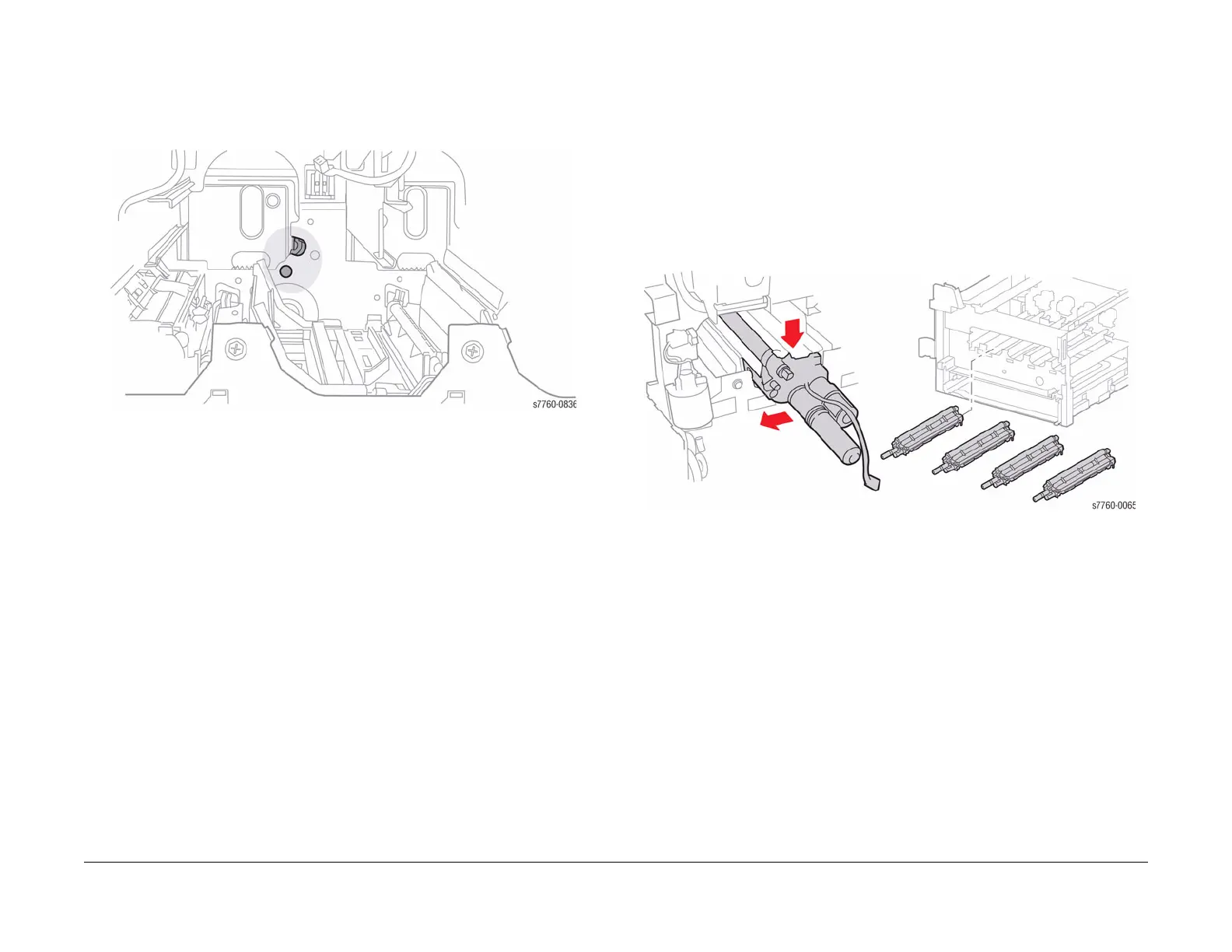
2. Remove the Developer Housing (Figure 1).
Figure 1 Removing Developer Housing