January 2010
4-41
Phaser 7760 Color Laser Printer
REP 9.8
Repairs and Adjustments
Revised
11. Clear the wiring harnesses from the Guide located on the lower left side of the assembly.
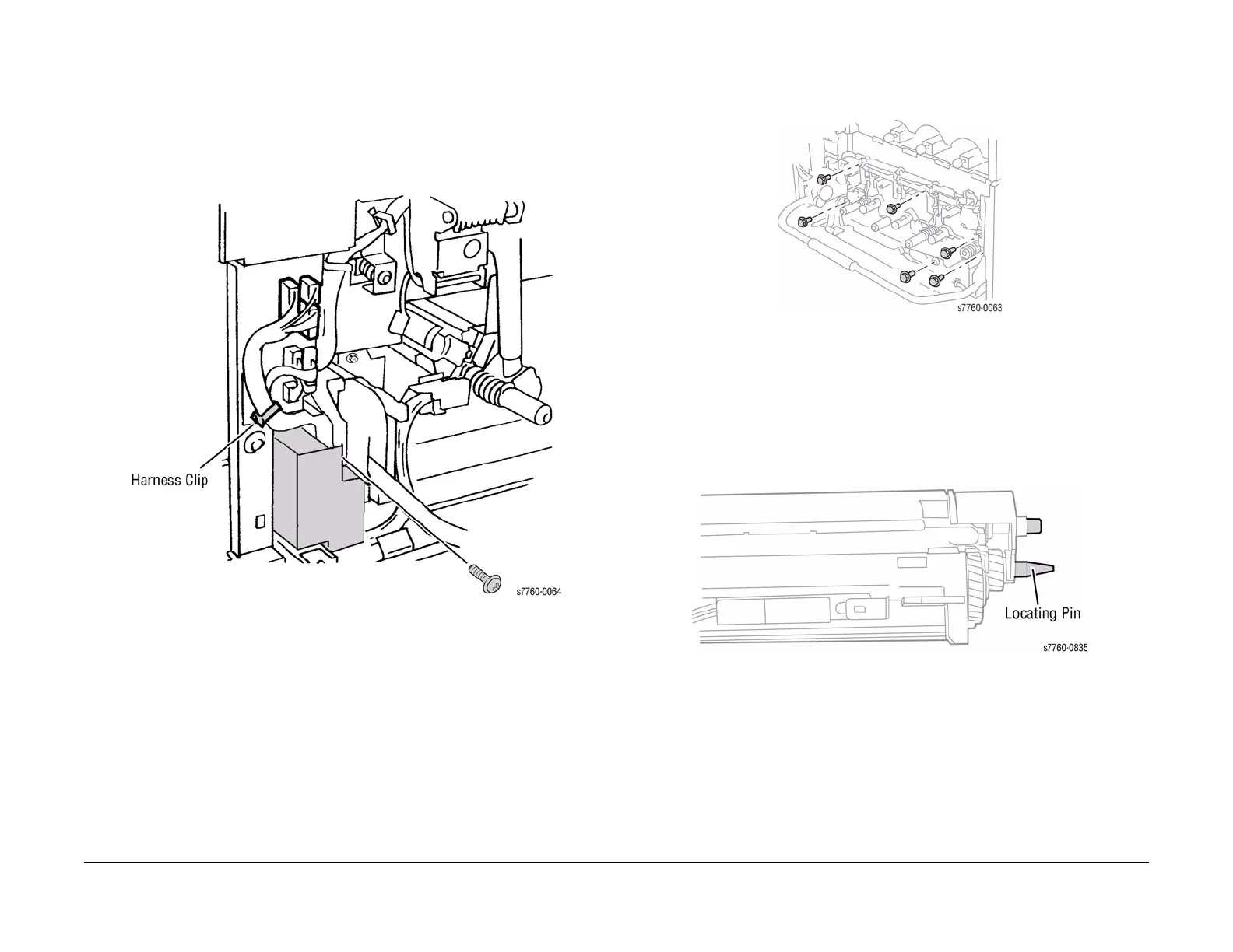
12. Disconnect Developer Housing Wiring Harnesses (Figure 2).
a. Open the Harness Clip and remove the harness.
b. Disconnect the 5 wiring harness P/Js.
c. Remove 1 screw from Inner Left Harness Cover and remove the Cover.
d. Remove the Developer Housing Harnesses from additional harness clips (not
shown, under the Harness Cover).
Figure 2 Disconnecting Developer Housing Wiring Harnesses
13. Removing the Plate Assembly (Figure 3).
a. Remove the 6 chrome plated screws securing the Plate to the Frame.
b. Remove the Imaging Unit Plate Assembly.
Figure 3 Removing Plate Assembly
Replacement
NOTE: Ensure the Developer Assemblies are fully and evenly seated when reinstalling the
Imaging Unit Plate. There is a locating Pin at the back of each Developer Housing Assembly.
Lightly tug the wires to ensure that they are not pinched by the Plate or the Developers while
reinstalling. Center the Connectors flat against the Wire Guide with the yellow Developer Con-
nector further to the right.
Figure 4 Locating Pin