January 2010
4-52
Phaser 7760 Color Laser Printer
REP 9.21
Revised
Repairs and Adjustments
REP 9.21 Left Lift Assembly
Parts List on PL 5.1
Removal
1. Open the Front Cover.
2. Remove Fuser Cover (REP 14.8).
3. Remove Waste Toner Cartridge.
4. Remove Waste Toner Cartridge Cover (REP 9.3).
5. Remove the Inner Cover (REP 14.10).
6. Release and move the IBT Cam Lever down.
7. Remove the Imaging Units.
8. Remove the Right Cover (REP 14.3).
9. Remove the IBT Belt Assembly (Accumulator Belt) (REP 9.15).
10. Remove the IBT Cam Lever (REP 9.18).
11. Remove the Rear Cover (REP 14.2).
12. Remove the Rear Left Middle Cover (REP 14.4).
13. Remove Tray 1 (MPT) (REP 7.1).
14. Remove the Left Cover Assembly (REP 8.1).
15. Remove the Registration Transport Assembly (REP 8.6).
16. Remove the Dispenser Cover (REP 9.6).
17. Remove the Agitator Motor Assembly (REP 9.13).
18. Remove the MOB Sensor Assembly (REP 9.14).
19. Remove the Left Hinge (REP 9.19).
NOTE: In next step, it may not be necessary to disconnect harnesses for Plate Assembly
(PL 4.2) to remove a Developer Housing.
20. Remove the Black Developer (REP 9.9).
21. Remove the K Erase Lamp/Rail (REP 9.25).
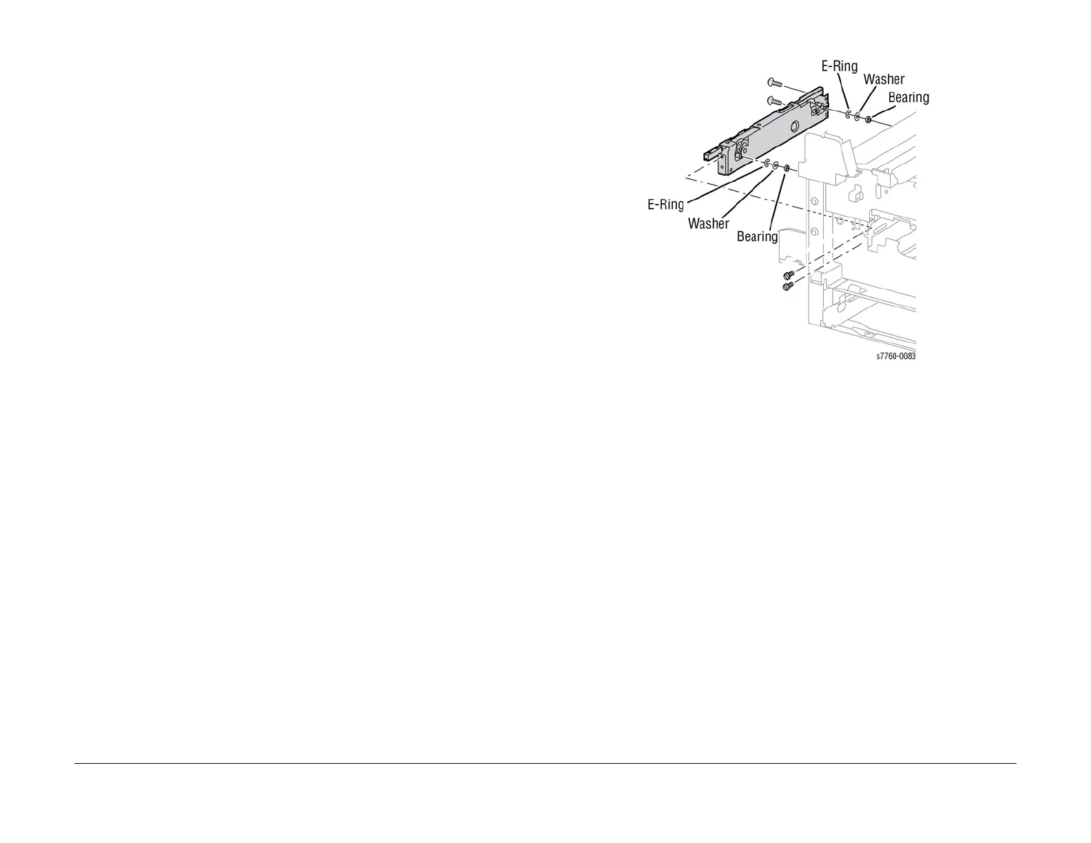
22. Removing the Left Lift Assembly (Figure 1).
CAUTION
The Washers can fall out into the lower metal cavity. Lay something underneath to catch
the Washers and screws.
NOTE: In next step, use a magnet to capture E-Ring and Washer while removing them.
a. Remove the E-Clips, washers, and bearings from the Left Lift Assembly Roller
Guides.
b. Partially remove the left hand side of the Main Level Assembly.
c. Remove the Left Hand Lever Hinge.
d. Remove the 4 screws securing the Left Lift Assembly Bracket and remove the
Bracket.
e. Remove the 4 screws and remove the Left Lift Assembly from the Printer.
Figure 1 Removing Left Xerographic Lift
Replacement
NOTE: When reinstalling the Left Lift Assembly, install the screws as follows: Upper Left,
Upper Right, then the Lower screws. Verify that the Timing Marks on the Main Level and the
Lift Jack Assembly align.
1. Installing the Left Lift Assembly.
a. Position the Lift in the frame.
b. Raise or lower the frame as required and push in or pull out the Lift Actuator as
required to engage the Lift bearings with slots in the frame.
c. Install the Upper Left screws, Upper Right screws, and Lower screws.
d. Install the 2 washers and 2 E-Rings.
2. Assemble the remaining machine components.