January 2010
4-53
Phaser 7760 Color Laser Printer
REP 9.21
Repairs and Adjustments
Revised
Aligning Lift Jack Assemblies
Visually examine both ends of the Accumulator Belt Assembly or Belt Lift Frame Assembly
while operating the Lift Handle to determine if the left or right end is out of alignment. Refer to
REP 9.20 or REP 9.21 to remove the affected Lift Jack Assembly. Once the Assembly is
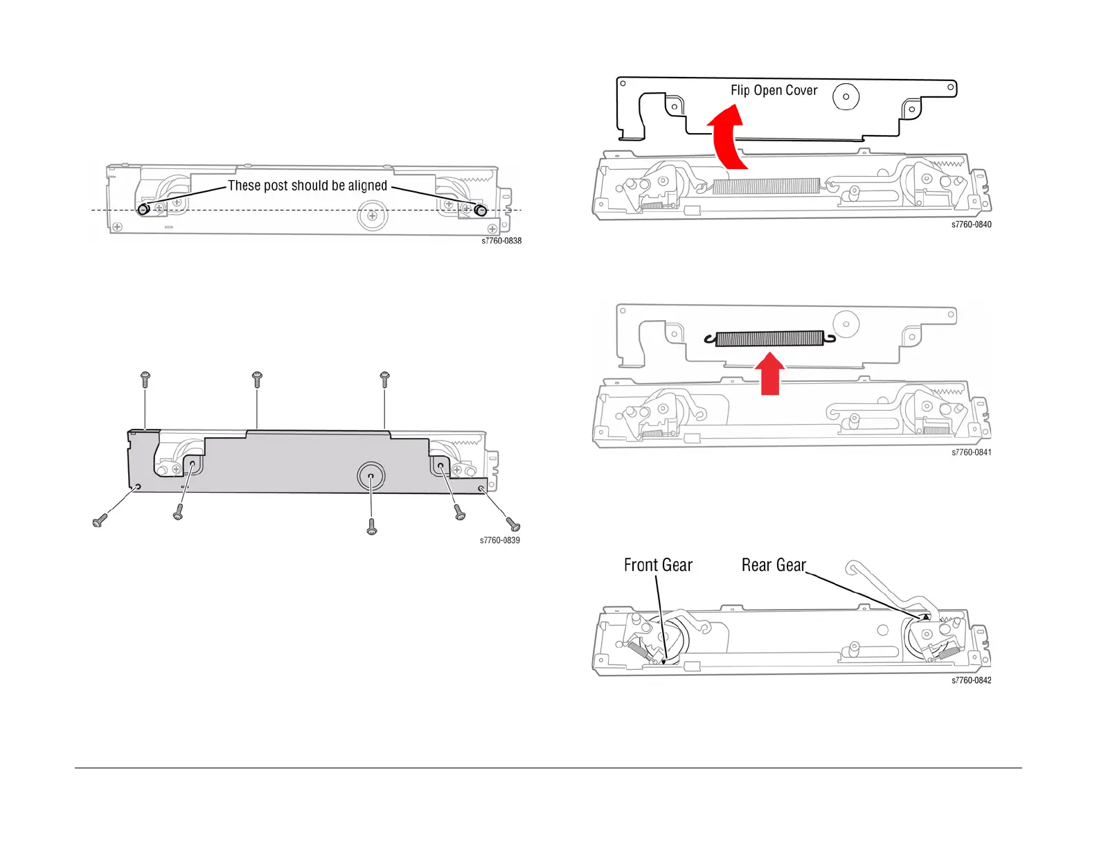
removed, check the alignment of the Lift Pins as shown in Figure 2. The center of both pins
should be the same distance from the bottom of the assembly.
Figure 2 Lift Pin Alignment
If the Lift Pins are misaligned, follow this procedure to realign the individual Gears with the
Rack.
1. Remove the 8 Cover screws from the Lift Jack Assembly (Figure 3).
Figure 3 Cover Screw Location
2. Flip open the Cover Plate (Figure 4).
Figure 4 Cover Removed
3. Remove the Tension Spring (Figure 5).
Figure 5 Tension Spring Location
4. Align the triangle marks on the Gears and the Rack by lifting the Gear Assemblies on their
mounting posts until they disengage from the Rack and rotating them until the triangle
align (Figure 6). Then reseat the Gear fully on its post.
Figure 6 Front and Rear Gears Aligned