January 2010
4-73
Phaser 7760 Color Laser Printer
REP 12.52
Repairs and Adjustments
Revised
REP 12.52 Finisher Punch Frame Assembly
Parts List on PL 21.5
Removal
1. Open the Front Door.
2. Remove the Rear Upper Cover (REP 12.41).
3. Remove the 2 screws securing the Punch Frame Assembly from the front of the Finisher
(Figure 1).
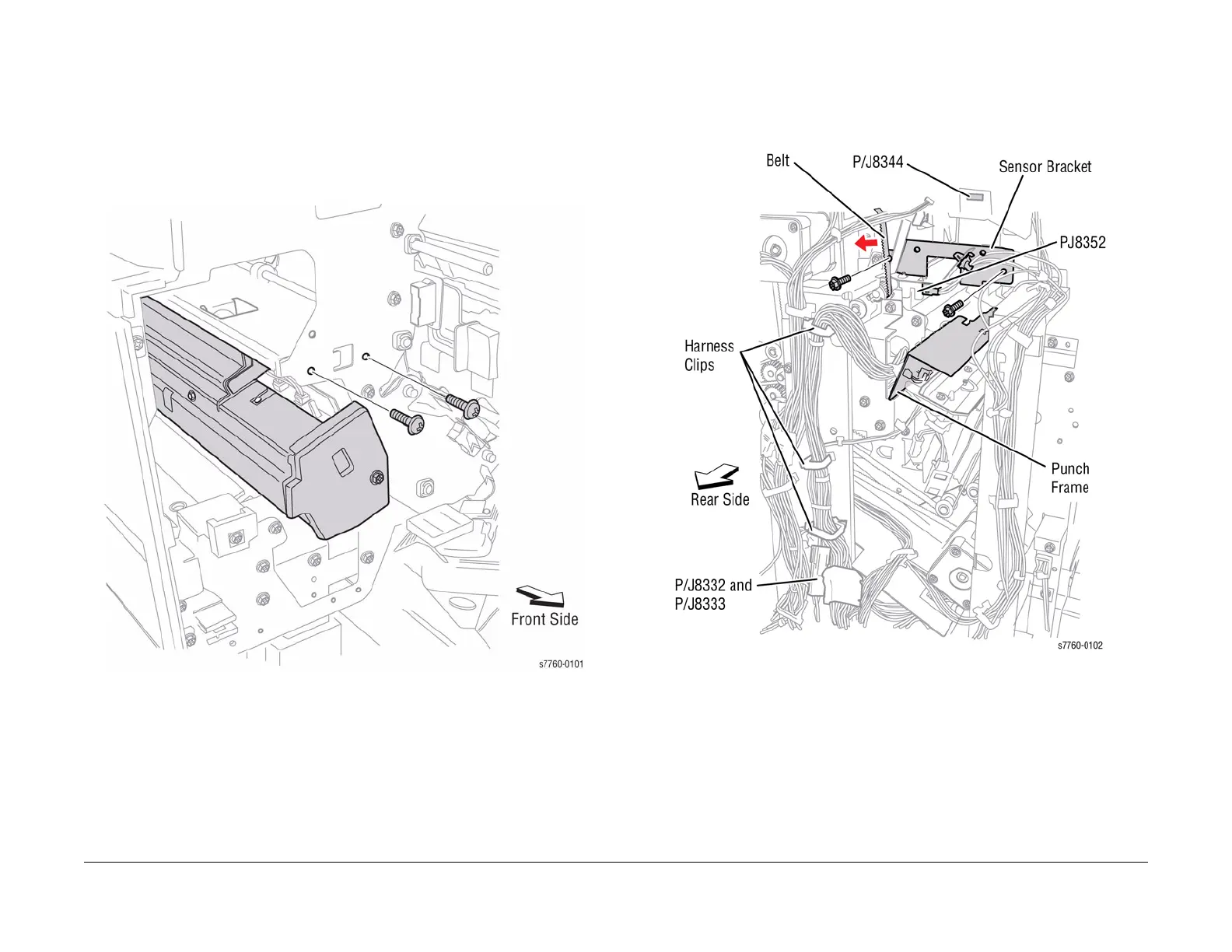
Figure 1 Removing Screws (Front Side of Finisher)
NOTE: In order to prevent from damaging the Registration Motor Drive Belt during the
next step, use caution when removing the Punch Frame Assembly from the Finisher.
4. Removing the Punch Frame Assembly (Figure 2).
a. Disconnect wiring harness J8344 (refer to Section 7, Finisher Top Rear View Plug/
Jack Locations - Figure 4). Open the Harness Clip and move the wiring harness to
the side.
b. Disconnect wiring harness P/J8352 and release the cable-tie.
c. Disconnect the wiring harnesses P/J8332, P/J8333 (refer to Section 7, Finisher Rear
View Plug/Jack Locations - Figure 2), and J8344.
d. Open the 3 harness clips and release the cable-tie.
e. Remove the 2 screws and the Punch Frame Assembly from the rear side of the Fin-
isher.
Figure 2 Removing the Punch Frame Assembly (Rear Side of Finisher)
Replacement
NOTE: Dress all cable slack toward the Punch Unit to prevent the Cables from binding.