Phaser 8400/8500/8550/8560 Color Printer Service Manual 8-9
Service Parts Disassembly
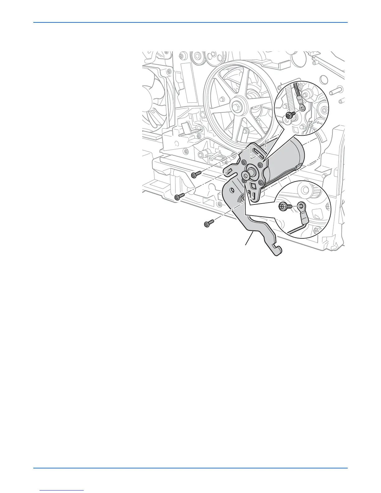
7. Remove 3 screws (3 coarse thread and 1 fine thread) from the spring
arm. The 3 screws securing the arm to the motor remain in place.
8. If replacing the motor, remove 3 motor screws to separate the motor from
the arm and remove the spring arm.
ep
acemen
o
e
Check that the spring arm screws are in the right locations, the
grounding connection is attached, and that the arm floats freely.
Screws in plastic are torqued to 12 in. lbs., metal to 15 in lbs., unless
otherwise specified. Also, if the spring arm has been removed from
the motor, torque the motor screws securing the spring arm to 20 in.-
lbs. Irreversible damage can result from over tightening screws into
plastic parts.
s8500-071
20 in-lbs.
Y-Axis Motor Assembly
 Loading...