2-22 Phaser 8400/8500/8550/8560 Color Printer Service Manual
Theory of Operation
I/O Board
All sensor and switch readings are input into the I/O Board. The I/O Board
translates these states into encoded information that it sends over a serial
data bus (I/O Board data cable) to the Electronics Module. The Electronics
Module has no direct connection to sensors, switches, or solenoids. In order
to activate a clutch or solenoid, the Electronics Module sends a command to
the I/O Board, which processes the command and activates the appropriate
device.
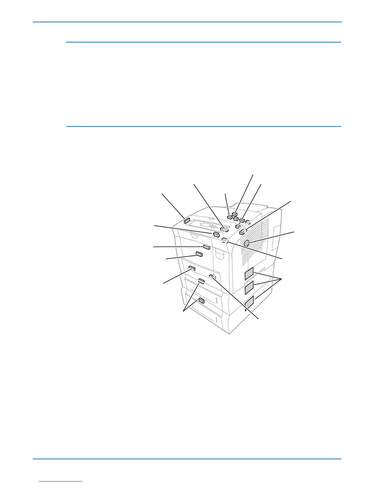
Sensors
Sensors throughout all the major subsystems provide indicators of vital print
operations. The following graphic identifies the location of the printer’s
sensors.
s8500-023
Exit Door Sensor
Strip Sensor
Paper Exit Sensor
Drum
Temperature
Sensor
Drum
Position
Encoder
Paper
Size Sensor
Preheater
Sensor
Media Width
Sensor
Deskew
Sensor
Pick Sensor
(525-sheet
Feeder)
Tray Empty
Sensor (Also in
Trays 3 & 4)
Ink Low
Ink Out
Front Door
Sensor
Tray Lift Sensor
(Also in Trays 3 & 4)
 Loading...