06/2014
4-64
WC 5022/5024
Version 1.0
Repairs and Asdjustments
REP 18.3.2 ESS/MCU PWB
Parts List on PL 18.3
Removal
WARNING
When turning OFF the power switch, check that the 'Data' lamp is OFF and that there is
no Job in progress.
Turn OFF the power switch and make sure that the screen display turns OFF.
Check that the power switch is OFF and unplug the power plug.
CAUTION
Static electricity may damage electrical parts.
Static electricity may damage electrical parts. Always wear a wrist band during servicing. If a
wrist band is not available, touch some metallic parts before servicing to discharge the static
electricity.
CAUTION
Do not get yourself hurt by a soldered portion on the back of the PWB.
1. [Net I/F PWB Type]
Remove the Net I/F PWB. (REP 18.3.1)
2. Remove the Rear Cover. (REP 19.4.1)
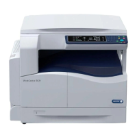
3. Disconnect the connector. (Figure 1)
a. Disconnect the connector (x19).
Figure 1 j0mg41854
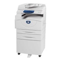
4. Remove the ESS/MCU PWB. (Figure 2)
a. Remove the screw (x6).
b. Release the hook and remove the ESS/MCU PWB.
Figure 2 j0mg41855
Replacement
1. To install, carry out the removal steps in reverse order.
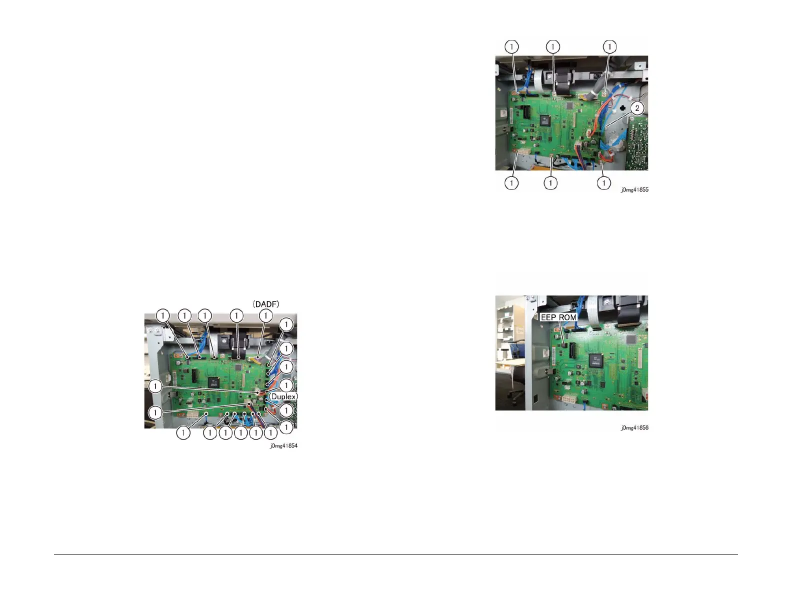
2. When replacing the ESS/MCU PWB, remove the EEP ROM from the old ESS/MCU PWB,
and install it to the new one. (Figure 3)
Figure 3 j0mg41856
3. Turning ON the power switch will cause 016-334 (NVM Data Mismatch) to be displayed.
(The Billing/Meter is stored in the EEP ROM at 2 locations. Since the ESS/MCU PWB is a
new one, it contains a different value.)
To take corrective action, enter the Diag Mode and input Clain-Link number "621-400" to
perform NVM matching.
For more details on the procedure, refer to [6.4.2.15 Checking and Repairing the Billing
Counter (621-400)].
 Loading...