u
Switches and Jumpers on the Terminal Board
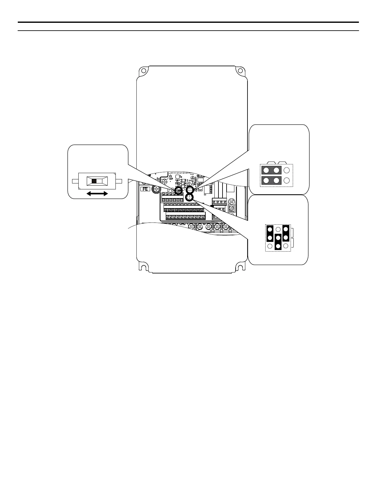
The terminal board is equipped with several switches used to adapt the drive I/Os to the external control signals. Figure
3.36 shows the location of these switches. Refer to Control I/O Connections on page 101 for setting instructions.
E(G)
IG R+ R- S+ S-
S1 S2 S3 S4 S5 S6 S7 S8 SN SC SP
V+ AC A1 A2 A3 FM AM AC 24VRP AC
M1 M2 M3 M4
MD ME MF
MA MB MC
Selection
V
AM
FM
I
Jumper S5
Terminal AM/FM Signal
DIP Switch S2
RS-422/485 Termination
Resistor
Off On
Jumper S1
A1/A2/A3 Volt/Curr.
Selection
V
I
A1 A2 A3
Figure 3.36 Locations of Jumpers and Switches on the Terminal Board
3.9 Control Circuit Wiring
100
YASKAWA SIEP YAIP1U 01C AC Drive - P1000 Technical Manual

 Loading...


