n
Serial Communication Terminals
Table 3.9 Control Circuit Terminals: Serial Communications
Type No. Signal Name Function (Signal Level)
MEMOBUS/Modbus
Communication
<1>
R+ Communications input (+)
MEMOBUS/Modbus communication: Use an
RS-422 or RS-485 cable to connect the drive.
RS-422/RS-485
MEMOBUS/Modbus
communication
protocol
115.2 kbps (max.)
R- Communications input (-)
S+ Communications output (+)
S- Communications output (-)
IG Shield ground 0 V
<1> Enable the termination resistor in the last drive in a MEMOBUS/Modbus network by setting DIP switch S2 to the ON position. Refer to the manual
section on Control I/O Connections for more information.
u
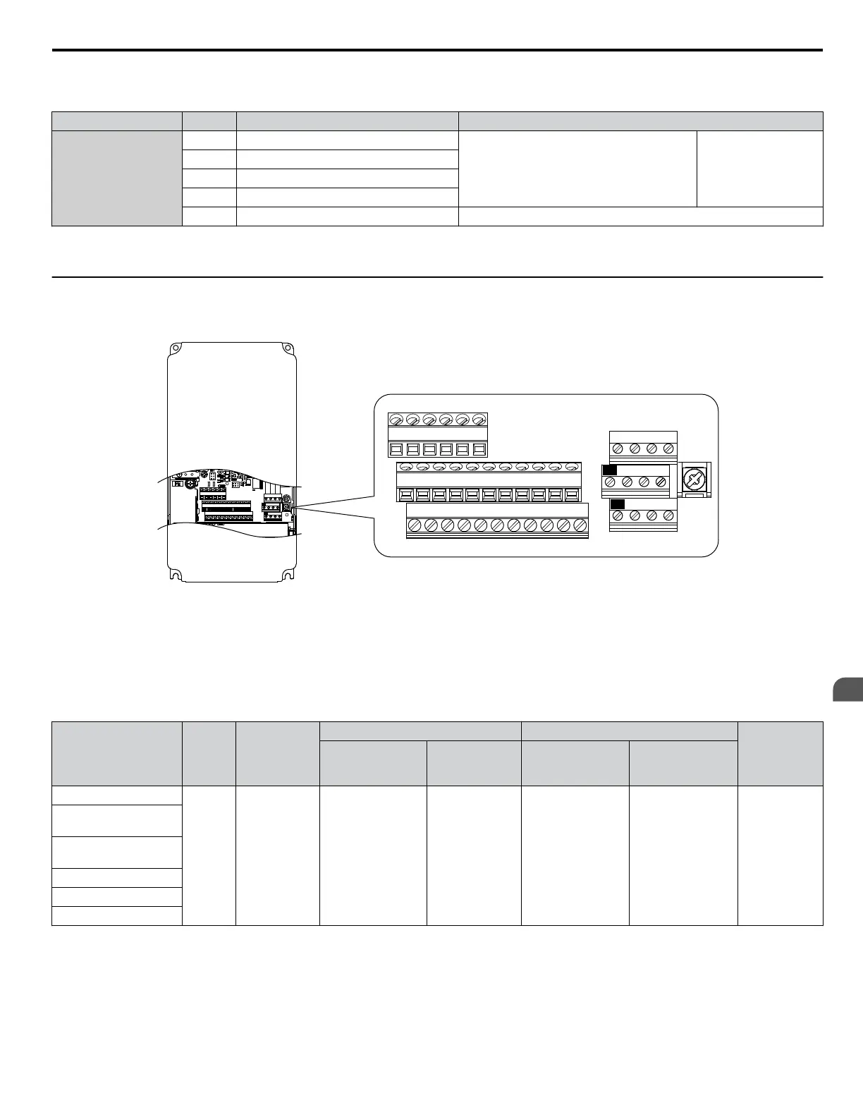
Terminal Configuration
The control circuit terminals are arranged as shown in Figure 3.31.
E(G)
IG R+ R- S+ S-
S1 S2 S3 S4 S5 S6 S7 S8 SN SC SP
V+ AC A1 A2 A3 FM AM AC 24VRP AC
M1 M2 M3 M4
MD ME MF
MA MB MC
E(G)
IG R+ R- S+ S-
S1 S2 S3 S4 S5 S6 S7 S8 SN SC SP
V+ AC A1 A2 A3 FM AM AC 24VRP AC
M1 M2 M3 M4
MD ME MF
MA MB MC
TB5
Figure 3.31 Control Circuit Terminal Arrangement
n
Wire Size and Torque Specifications
Select appropriate wire type and gauges from Table 3.10. For simpler and more reliable wiring, use crimp ferrules on the wire
ends. Refer to Table 3.11 for ferrule terminal types and sizes.
Table 3.10 Wire Gauges
Terminal
Screw
Size
Tightening
Torque
N•m
(lb. in)
Bare Wire Terminal Ferrule-Type Terminal
Wire Type
Applicable
wire size
mm
2
(AWG)
Recomm.
wire size
mm
2
(AWG)
Applicable
wire size
mm
2
(AWG)
Recomm.
wire size
mm
2
(AWG)
S1-S8, SC, SN, SP
M3
0.5 to 0.6
(4.4 to 5.3)
Stranded wire:
0.2 to 1.0
(24 to 16)
Solid wire:
0.2 to 1.5
(24 to 16)
0.75 (18)
0.25 to 0.5
(24 to 20)
0.5 (20)
Shielded wire,
etc.
RP, V+, A1, A2, A3,
AC, 24 V
MA, MB, MC, MD, ME,
MF
M1-M4
FM, AM, AC
R+, R-, S+, S-, IG
3.9 Control Circuit Wiring
YASKAWA SIEP YAIP1U 01C AC Drive - P1000 Technical Manual
97
3
Electrical Installation

 Loading...


