Setting 0: Digital Output Only
Setting 1: Run
Setting 2: Run - PI Disable
Setting 3: Allow Alternation
When Sequence Selection is set to Allow Alternation and that timer is enabled (S2-03, S2-08, S2-13, S2-18 > 0), the drive
will only allow MEMOBUS alternation to occur during the time specified in the corresponding Sequence Timer. Alternation
is disabled when the timer deactivates.
n
S2-05/S2-10/S2-15/S2-20: Sequence Timers 1/2/3/4 Reference Source
Selects the frequency reference source used for running the drive when sequence timers 1 to 4 are active (only applicable when
S2-04/S2-09/S2-14/S2-19 are set to 1 or 2).
No. Name Setting Range Default
S2-05 Sequence Timer 1 Reference Source 0 to 7 0
S2-10 Sequence Timer 2 Reference Source 0 to 7 0
S2-15 Sequence Timer 3 Reference Source 0 to 7 0
S2-20 Sequence Timer 4 Reference Source 0 to 7 0
Setting 0: Operator (d1-01)
Setting 1: Operator (d1-02)
Setting 2: Operator (d1-03)
Setting 3: Operator (d1-04)
Setting 4: Terminals
Setting 5: Serial Communication
Setting 6: Option Card
Setting 7: Pulse Input
u
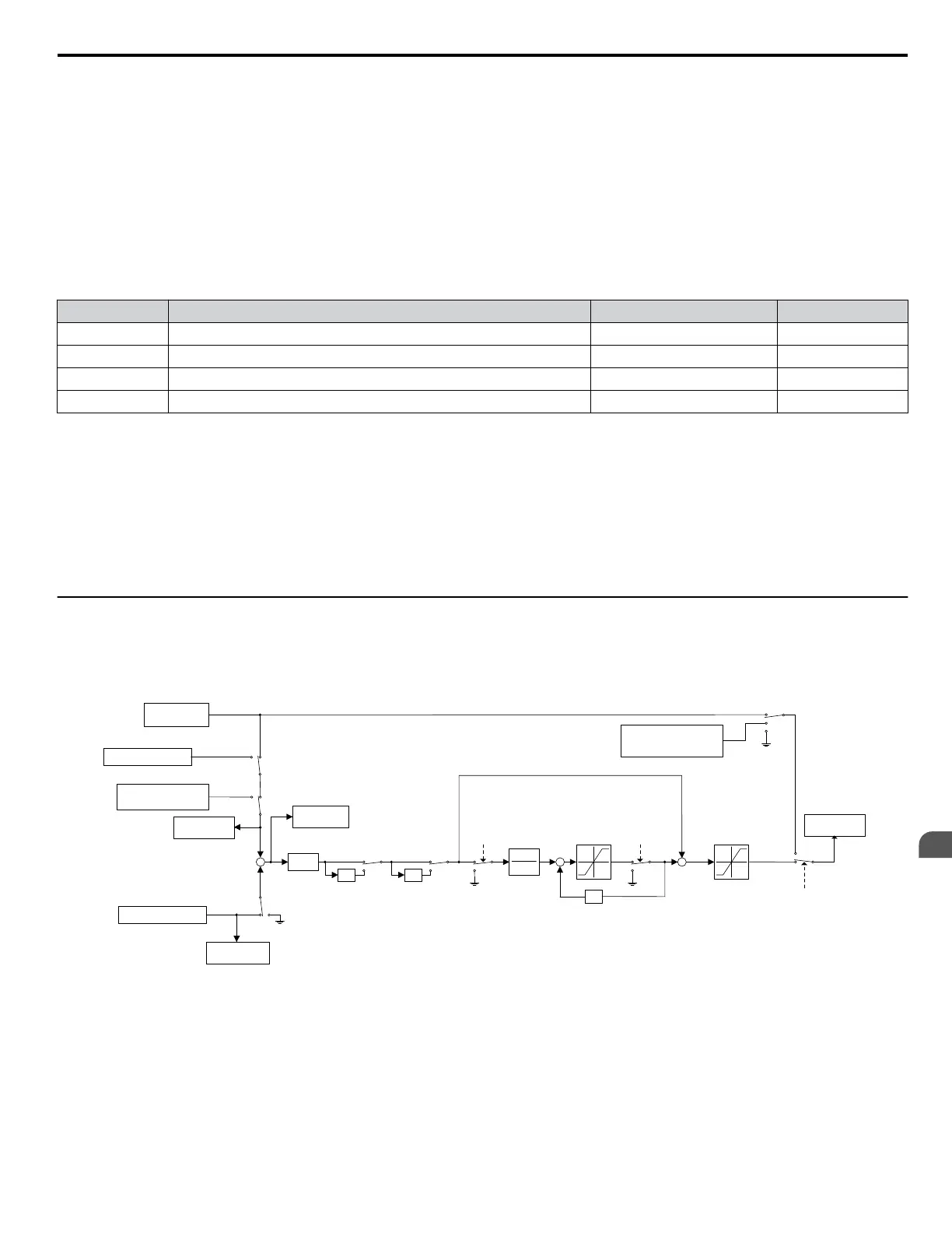
S3: Secondary PI (PI2) Control
The drive has a built in PI (Proportional + Integral) controller that can be used for closed loop control of system variables such
as pressure or temperature. The difference between the target and the feedback value (deviation) is fed into the PI controller
and the PI controller outputs the frequency to U5-oo for monitoring. Refer to b5: PID Control on page 160 for details.
S3-06
PI2 P Gain
-1
PI2 I Time
1
S3-07
+
+
S3-08
PI2 I Limit
<1>
z
-1
PI2 Invert
Multi-function
Input Closed
+
+
Upper Limit:
S3-09
PI2 Output Upper
Limit
Lower Limit:
S3-10
PI2 Output Lower Limit
U5-19
PI2 Input
-1
S3-11 = 0
S3-11 = 1
PI2
Integral
Hold Multi-
function
Input
PI2 Integral
Reset Multi-
Function Input
MEMOBUS 000Dh
PI2 Setpoint
MEMOBUS
000FH
bit 4 = 1
S3-05
PI Setpoint
+
Terminal A1/A2/A3
-
U5-17
PI2 Setpoint
U5-18
PI2 Feedback
U5-20
PI2 Output
Lower Limit:
S3-10
PI2 Output Lower Limit
PI2 Disable
Multi-function
Input <2>
S3-12
0
1
2
<1> Actual integral limit is calculated as follows:
Upper limit = Min (S3-08, S3-09 - PI2 P portion)
Lower limit = Min (-S3-08, S3-10 - PI2 P portion)
<2> When PI2 Disable multi-function input is closed, set PI Integrator as follows:
S3-12 = 1: PI I Value = S3-10
S3-12 = 2: PI I Value = S3-05
H3-02/
H3-06/
H3-10=25
Terminal A1/A2/A3
H3-02/H3-06/
H3-10=26
Figure 5.94 PI2 Block Diagram
n
S3-01: Secondary PI Enable Selection
Determines when the secondary PI controller is enabled.
5.11 S: Special Application
YASKAWA SIEP YAIP1U 01C AC Drive - P1000 Technical Manual
281
5
Parameter Details

 Loading...


