3.10 Control I/O Connections
u
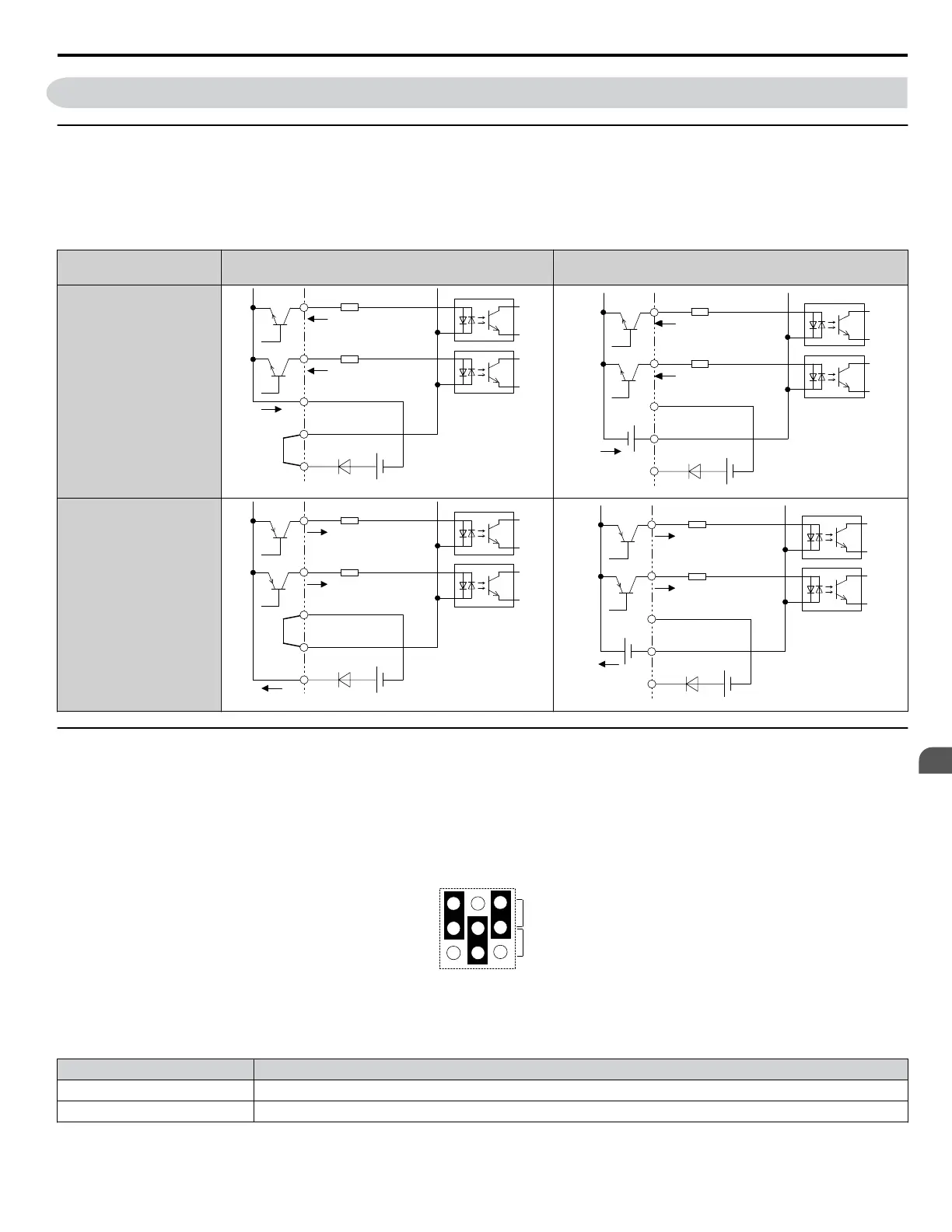
Sinking/Sourcing Mode for Digital Inputs
Use the wire jumper between terminals SC and SP or SC and SN to select between Sink mode, Source mode or external power
supply for the digital inputs S1 to S8 as shown in Table 3.12 (Default: Sink mode, internal power supply).
NOTICE: Do not short terminals SP and SN. Failure to comply will damage the drive.
Table 3.12 Digital Input Sink/Source/External Power Supply Selection
Mode
Drive Internal Power Supply
(Terminals SN and SP)
External 24 Vdc Power Supply
Sinking Mode (NPN)
SC
S8
S7
24 Vdc
SP
SN
SC
S8
S7
24 Vdc
SP
SN
External
24 Vdc ±10%
Sourcing Mode (PNP)
SC
S8
S7
24 Vdc
SP
SN
SC
S8
S7
24 Vdc
SP
SN
External
24 Vdc ±10%
u
Terminals A1, A2, and A3 Input Signal Selection
Terminals A1, A2, and A3 can be used to input either a voltage or a current signal. Select the signal type using jumper S1 as
explained in Table 3.13. Set parameters H3-01, H3-05, and H3-09 accordingly as shown in Table 3.14. Refer to Switches
and Jumpers on the Terminal Board on page 100 for locating jumper S1.
Note: If terminals A1 and A2 are both set for frequency bias (H3-02 = 0 and H3-10 = 0), both input values will be combined to create the frequency
reference.
Figure 3.37 Terminal A2 Set to Current Input; A1 and A3 Set to Voltage Input
Table 3.13 Jumper S1 Settings
Setting Description
V (top position) Voltage input (-10 to +10 V or 0 to 10 V)
I (bottom position) Current input (4 to 20 mA or 0 to 20 mA)
3.10 Control I/O Connections
YASKAWA SIEP YAIP1U 01C AC Drive - P1000 Technical Manual
101
3
Electrical Installation

 Loading...


