Setting 5: UL3, UL4 at speed agree (Alarm)
Undertorque detection is active only when the output speed is equal to the frequency reference, i.e., no detection during
acceleration and deceleration. The operation continues after detecting overtorque and triggering a UL3/UL4 alarm.
Setting 6: UL3, UL4 at Run (Alarm)
Undertorque detection works as long as the Run command is active. The operation continues after detecting overtorque and
triggering a UL3/UL4 alarm.
Setting 7: UL3, UL4 at Speed Agree (Fault)
Undertorque detection is active only when the output speed is equal to the frequency reference, i.e., no detection during
acceleration and deceleration. The operation stops and triggers a UL3/UL4 fault.
Setting 8: UL3, UL4 at run (Fault)
Undertorque detection works as long as a Run command is active. The operation stops and triggers a UL3/UL4 fault.
Setting 9: UL6 at speed agree (Alarm)
Setting 10: UL6 during run (Alarm)
Setting 11: UL6 at speed agree (Fault)
Setting 12: UL6 during run (Fault)
n
L6-02, L6-05: Torque Detection Level 1, 2
These parameters set the detection levels for torque detection functions 1 and 2 as a percentage of the drive rated output current.
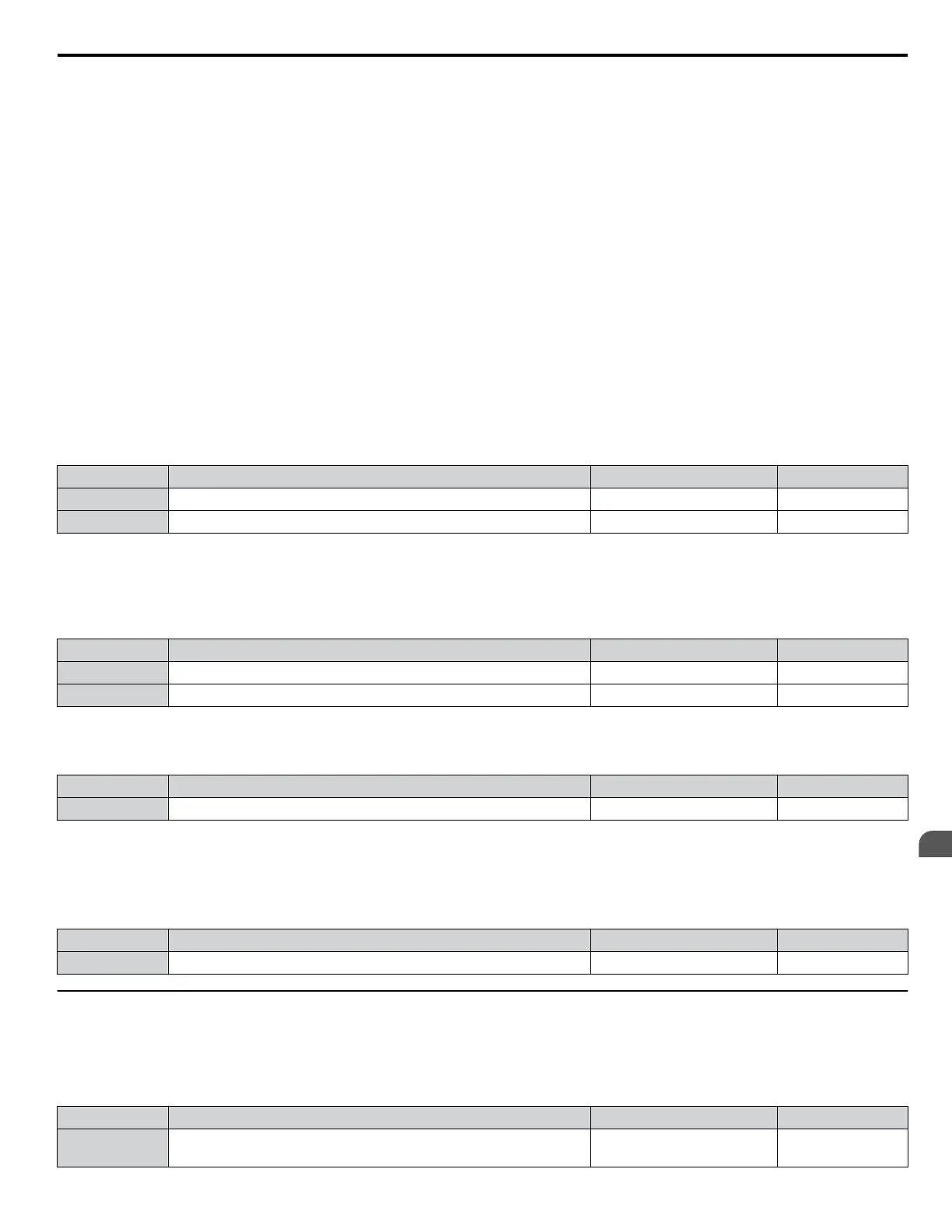
No. Name Setting Range Default
L6-02 Torque Detection Level 1 0 to 300% 15%
L6-05 Torque Detection Level 2 0 to 300% 150%
Note:
The torque detection level 1 (L6-02) can also be supplied by an analog input terminal set to H3-oo = 7. Here, the analog value has priority
and the setting in L6-02 is disregarded. Torque detection level 2 (L6-05) cannot be set by an analog input.
n
L6-03, L6-06: Torque Detection Time 1, 2
These parameters determine the time required to trigger an alarm or fault after exceeding the levels in L6-02 and L6-05.
No. Name Setting Range Default
L6-03 Torque Detection Time 1 0.0 to 10.0 s 10.0 s
L6-06 Torque Detection Time 2 0.0 to 10.0 s 0.1 s
n
L6-13: Motor Underload Protection Selection
Sets the motor underload protection (UL6) based on motor load.
No. Name Setting Range Default
L6-13 Motor Underload Protection Selection 0, 1 0
Setting 0: Base frequency enable
Setting 1: Max frequency enable
n
L6-14: Motor Underload Protection Level at Minimum Frequency
Sets the motor underload protection (UL6) based on motor load.
No. Name Setting Range Default
L6-14 Motor Underload Protection Level at Minimum Frequency 0 to 300% 15%
u
L8: Drive Protection
n
L8-01: Internal Dynamic Braking Resistor Protection Selection (ERF type)
Selects the dynamic braking resistor protection when using an optional heatsink mounted braking resistor (ERF type, 3% ED).
Note:
No. Name Setting Range Default
L8-01
Internal Dynamic Braking Resistor Protection Selection
(ERF type)
0, 1 0
5.8 L: Protection Functions
YASKAWA SIEP YAIP1U 01C AC Drive - P1000 Technical Manual
257
5
Parameter Details

 Loading...


