u
Installing a Molded Case Circuit Breaker (MCCB) or Ground Fault Circuit Interrupter
(GFCI)
Install an MCCB or GFCI for line protection between the power supply and the main circuit power supply input terminals
R/L1, S/L2, and T/L3. This protects the main circuit and devices wired to the main circuit while also providing overload
protection.
NOTICE: Prevent Equipment Damage. Install a fuse and a GFCI to models 4A0930 and 4A1200, Failure to comply may result in damage
to the power supply in the event of a short circuit.
Consider the following when selecting and installing an MCCB or GFCI:
• The capacity of the MCCB or GFCI should be 1.5 to 2 times the rated output current of the drive. Use an MCCB or GFCI
to keep the drive from faulting out instead of using overheat protection (150% for one minute at the rated output current).
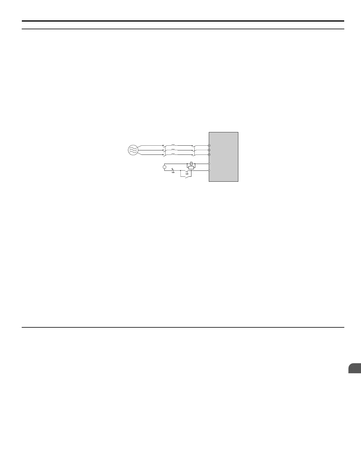
• If several drives are connected to one MCCB or GFCI that is shared with other equipment, use a sequence that shuts the
power OFF when errors are output by using magnetic contactor (MC) as shown in Figure 8.13.
R/L1
MB
MCCB or GFCI
A
B
MC
MC
MC
MC
S/L2
T/L3
C
SA
A – Power supply
B – Drive
C – Control power supply
Figure 8.13 Power Supply Interrupt Wiring (Example)
WARNING! Electrical Shock Hazard. Disconnect the MCCB (or GFCI) and MC before wiring terminals. Failure to comply may result in
serious injury or death.
n
Application Precautions when Installing a GFCI
Drive outputs generate high-frequency leakage current as a result of high-speed switching. Install a GFCI on the input side of
the drive to switch off potentially harmful leakage current.
Factors in determining leakage current:
• Size of the AC drive
• AC drive carrier frequency
• Motor cable type and length
• EMI/RFI filter
If the GFCI trips spuriously, consider changing these items or use a GFCI with a higher trip level.
Note: Choose a GFCI designed specifically for an AC drive. The operation time should be at least 0.1 s with sensitivity amperage of at least 200
mA per drive. The output waveform of the drive and built-in EMC filter may cause an increase in leakage current. This may in turn cause
the leakage breaker to malfunction. Increase the sensitivity amperage or lower the carrier frequency to correct the problem.
u
Installing a Magnetic Contactor at the Power Supply Side
Install a magnetic contactor (MC) to the drive input for the purposes explained below.
n
Disconnecting the Power Supply
Shut off the drive with an MC when a fault occurs in any external equipment such as braking resistors.
NOTICE: Do not connect electromagnetic switches or MCs to the output motor circuits without proper sequencing. Improper sequencing of
output motor circuits could result in damage to the drive.
NOTICE: Install an MC on the input side of the drive when the drive should not automatically restart after power loss. To get the full
performance life out of the electrolytic capacitors and circuit relays, refrain from switching the drive power supply off and on more than once
every 30 minutes. Frequent use can damage the drive. Use the drive to stop and start the motor.
NOTICE: Use a magnetic contactor (MC) to ensure that power to the drive can be completely shut off when necessary. The MC should be
wired so that it opens when a fault output terminal is triggered.
Note: 1. Install an MC to the drive input side to prevent the drive from restarting automatically when power is restored after momentary power
loss.
2. Set up a delay that prevents the MC from opening prematurely to continue operating the drive through a momentary power loss.
8.5 Installing Peripheral Devices
YASKAWA SIEP YAIP1U 01C AC Drive - P1000 Technical Manual
385
8
Peripheral Devices &
Options

 Loading...


