Setting 1: Enabled (6 Hz and above)
Slip compensation is enabled during regenerative operation. It will not be active at output frequencies below 6 Hz.
Setting 2: Enabled (compensation provided wherever possible)
Slip compensation is enabled during regenerative operation and at frequencies as low as 2 Hz. The drive uses the motor rated
slip set to E2-02 to automatically calculate the frequency range where compensation will be disabled.
u
C4: Torque Compensation
The torque compensation function compensates for insufficient torque production at start-up or when a load is applied.
Note: Set the motor parameters and V/f pattern properly before setting torque compensation parameters.
n
C4-01: Torque Compensation Gain
Sets the gain for the torque compensation function.
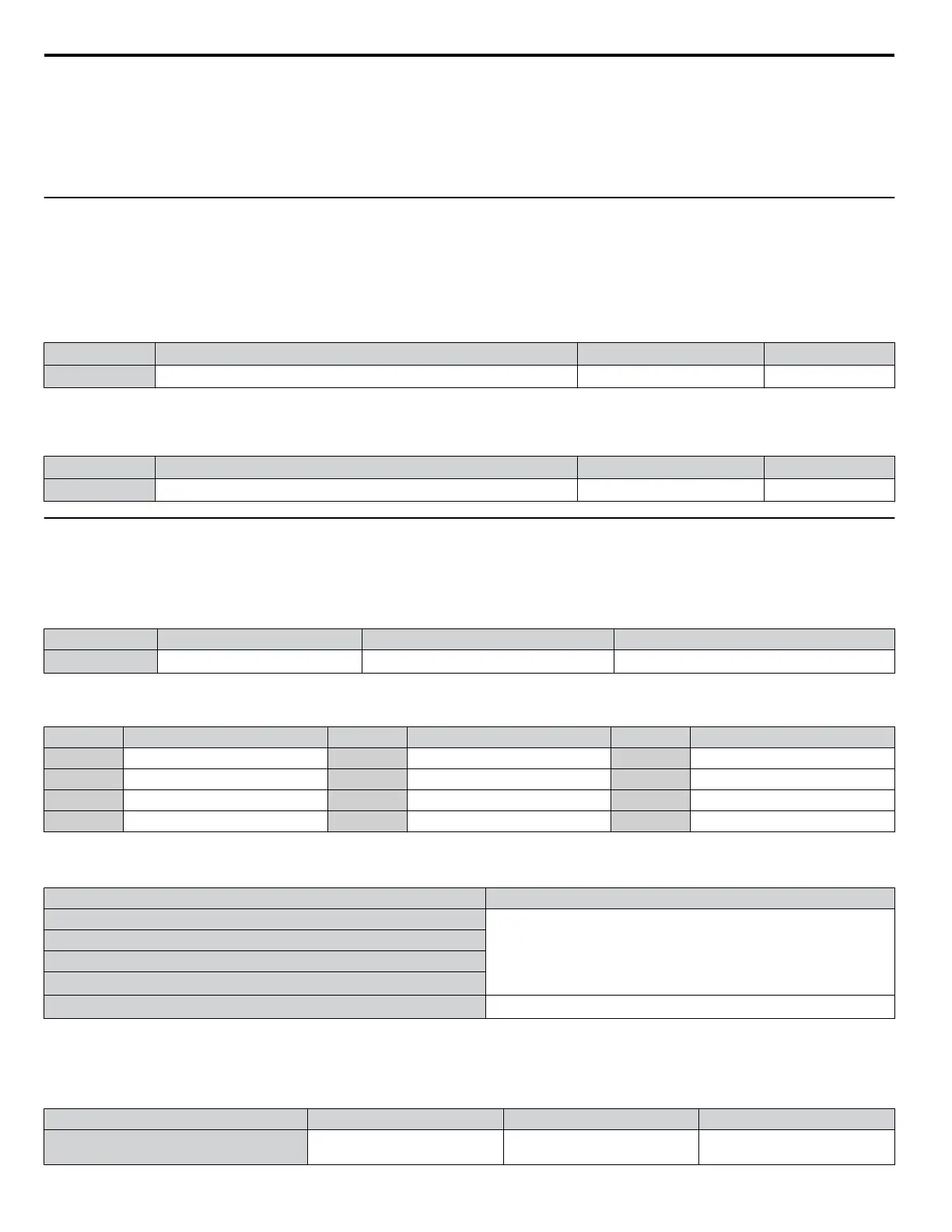
No. Parameter Name Setting Range Default
C4-01 Torque Compensation Gain 0.00 to 2.50 1.00
n
C4-02: Torque Compensation Primary Delay Time 1
Sets the delay time used for applying torque compensation.
No. Parameter Name Setting Range Default
C4-02 Torque Compensation Primary Delay Time 1 0 to 60000 ms 200 ms
u
C6: Carrier Frequency
n
C6-02: Carrier Frequency Selection
Sets the switching frequency of the drive output transistors. Changes to the switching frequency lower audible noise and reduce
leakage current.
No. Parameter Name Setting Range Default
C6-02 Carrier Frequency Selection
1 to 9; A, F
<1>
7
<1> The setting range is 1, 2, and F for models 4A0930 and 4A1200
Settings:
C6-02 Carrier Frequency C6-02 Carrier Frequency C6-02 Carrier Frequency
1 2.0 kHz 5 12.5 kHz 9 Swing PWM 3
2 5.0 kHz 6 15.0 kHz A Swing PWM 4
3 8.0 kHz 7 Swing PWM 1 B to E: No setting possible
4 10.0 kHz 8 Swing PWM 2 F User defined (C6-03 to C6-05)
Note: Swing PWM uses a carrier frequency of 2.0 kHz as a base, then applies a special PWM pattern to reduce the audible noise.
Guidelines for Carrier Frequency Parameter Setup
Symptom Remedy
Speed and torque are unstable at low speeds
Lower the carrier frequency.
Noise from the drive affects peripheral devices
Excessive leakage current from the drive
Wiring between the drive and motor is too long
<1>
Audible motor noise is too loud
Increase the carrier frequency or use Swing PWM.
<2>
<1> The carrier frequency may need to be lowered if the motor cable is too long. Refer to Table 5.14.
<2> The default carrier frequency is Swing PWM (C6-02 = 7), using a 2 kHz base. Increasing the carrier frequency is permissible , however the drive
rated current is reduced when the carrier frequency is increased.
Table 5.14 Wiring Distance and Carrier Frequency
Wiring Distance Up to 50 m Up to 100 m Greater than 100 m
Recommended setting value for C6-02 1 to F (up to 15 kHz)
1 to 2 (up to 5 kHz),
7 (Swing PWM)
1 (up to 2 kHz), 7 (Swing PWM)
5.3 C: Tuning
180
YASKAWA SIEP YAIP1U 01C AC Drive - P1000 Technical Manual

 Loading...


