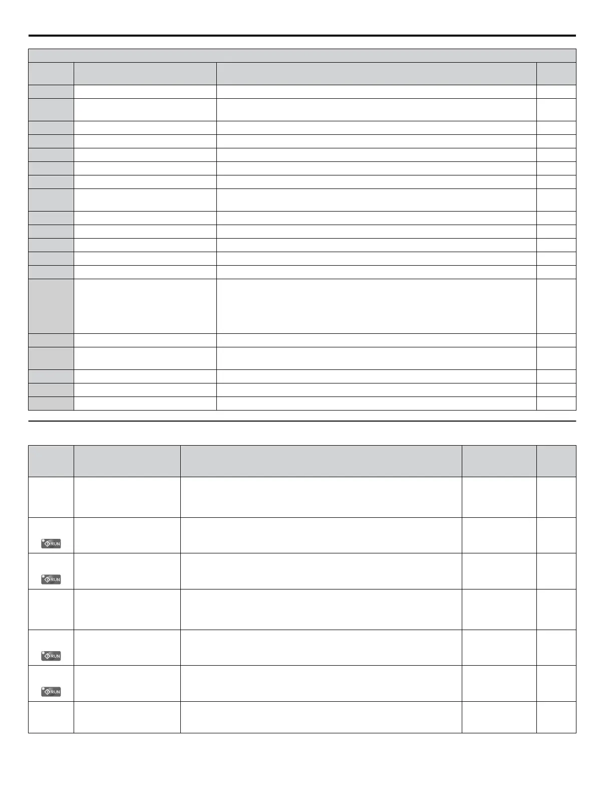
H3 Multi-Function Analog Input Settings
H3-oo
Setting
Function Description Page
0 Frequency bias 10 V = E1-04 (maximum output frequency) 228
1 Frequency gain
0 to 10 V signal allows a setting of 0 to 100%. -10 to 0 V signal allows a setting of -100
to 0%.
228
2 Auxiliary frequency reference 1 10 V = E1-04 (maximum output frequency) 228
3 Auxiliary frequency reference 2 10 V = E1-04 (maximum output frequency) 228
4 Output voltage bias 10 V = E1-05 (motor rated voltage) 228
5 Accel/decel time gain 10 V = 100% 228
6 DC Injection Braking current 10 V = Drive rated current 229
7
Overtorque/undertorque
detection level
10 V = Drive rated current (V/f)
229
8 Stall Prevention level during run 10 V = Drive rated current 229
9 Output frequency lower limit level 10 V = E1-04 (maximum output frequency) 229
B PID feedback 10 V = 100% 229
C PID setpoint 10 V = 100% 229
D Frequency bias 10 V = E1-04 (maximum output frequency) 229
E Motor Temperature (PTC Input)
10 V = 100%
Note:
A 12 kΩ resistor must be connected between one of the terminals A1, A2,
or A3 and V+ for PTC functionality. Connect the 12 kΩ resistor to the same
terminal as the PTC input. Do not connect terminals V+ to AC, or damage
to the drive may result.
230
16 Differential PID feedback 10 V = 100% 230
17 Motor Thermistor (NTC)
10 V = -9 °C
0 V = 234 °C
230
1F Through mode Set this value when using the terminal in the pass-through mode. 230
25 Secondary PI Setpoint 10 V = S3-02 (maximum output frequency) 230
26 Secondary PI Feedback 10 V = S3-02 (maximum output frequency) 230
u
H4: Analog Outputs
No.
(Addr.
Hex)
Name Description Values Page
H4-01
(41D)
Multi-Function Analog
Output Terminal FM
Monitor Selection
Selects the data to be output through multi-function analog output terminal
FM.
Set the desired monitor parameter to the digits available in Uo-oo.
For example, enter “103” for U1-03.
Default: 102
Range: 000 to 999
230
H4-02
(41E)
Multi-Function Analog
Output Terminal FM Gain
Sets the signal level at terminal FM that is equal to 100% of the selected
monitor value.
Default: 100.0%
Min.: -999.9
Max.: 999.9
230
H4-03
(41F)
Multi-Function Analog
Output Terminal FM Bias
Sets the signal level at terminal FM that is equal to 0% of the selected monitor
value.
Default: 0.0%
Min.: -999.9
Max.: 999.9
230
H4-04
(420)
Multi-Function Analog
Output Terminal AM
Monitor Selection
Selects the data to be output through multi-function analog output terminal
AM.
Set the desired monitor parameter to the digits available in Uo-oo.
For example, enter “103” for U1-03.
Default: 103
Range: 000 to 999
230
H4-05
(421)
Multi-Function Analog
Output Terminal AM Gain
Sets the signal level at terminal AM that is equal to 100% of the selected
monitor value.
Default: 50.0%
Min.: -999.9
Max.: 999.9
230
H4-06
(422)
Multi-Function Analog
Output Terminal AM Bias
Sets the signal level at terminal AM that is equal to 0% of the selected monitor
value.
Default: 0.0%
Min.: -999.9
Max.: 999.9
230
H4-07
(423)
Multi-Function Analog
Output Terminal FM Signal
Level Selection
0: 0 to 10 V
1: -10 to 10 V
2: 4 to 20mA
Default: 0
Range: 0 to 2
231
B.8 H Parameters: Multi-Function Terminals
460
YASKAWA SIEP YAIP1U 01C AC Drive - P1000 Technical Manual

 Loading...


