C.9 MEMOBUS/Modbus Data Table
The tables below list all MEMOBUS/Modbus data.
The MEMOBUS register hex addresses for parameters are listed beginning on page 433.
u
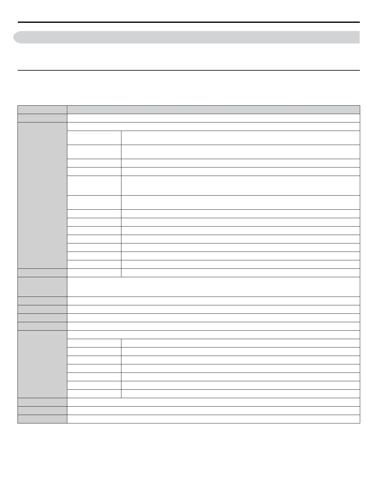
Command Data
It is possible to both read and write command data.
Note: Bits that are not used should be set to 0. Refrain from writing to reserved registers.
Register No. Contents
0000H Reserved
0001H
Operation Commands and Multi-function Inputs
bit 0
H5-12 = 0: Forward Run Command (0 = Stop, 1 = Forward Run)
H5-12 = 1: Run Command (0 = Stop, 1 = Run)
bit 1
H5-12 = 0: Reverse Run Command (0 = Stop, 1 = Reverse Run)
H5-12 = 1: Forward/Reverse (0 = Forward, 1 = Reverse)
bit 2 External Fault (EF0)
bit 3 Fault Reset
bit 4
Multi-Function Input 1
Function is ComRef when H1-01 = 40 (Forward/Stop). Refer to d: Reference Settings on page 182 for
ComRef explanations.
bit 5
Multi-Function Input 2
Function is ComCtrl when H1-02 = 41 (Reverse/Stop).
bit 6 Multi-Function Input 3
bit 7 Multi-Function Input 4
bit 8 Multi-Function Input 5
bit 9 Multi-Function Input 6
bit A Multi-Function Input 7
bit B Multi-Function Input 8
bit C to F Reserved
0002H Frequency Reference Units are determined by parameter o1-03.
0003H
Output voltage gain/
Unit: 0.1%
Range: 20 (2.0%) to 2000 (200.0%), Default when power on: 1000 (100.0%)
0004H to 0005H Reserved
0006H PID Target, 0.01% units, signed
0007H Analog Output Terminal FM Setting (10 V / 4000 H)
0008H Analog Output Terminal AM Setting (10 V / 4000 H)
0009H
Settings for Multi-Function Digital Outputs
bit 0 Multi-Function Contact Output (Terminal M1-M2)
bit 1 Multi-Function Contact Output (Terminal M3-M4)
bit 2 Multi-Function Contact Output (Terminal MD-MF)
bit 3 to 5 Reserved
bit 6 Enables the function in bit 7
bit 7 Fault Contact Output (terminal MA/MB-MC)
bit 8 to F Reserved
000AH to 000CH Reserved
000DH PI2 Setpoint
000EH Reserved
C.9 MEMOBUS/Modbus Data Table
520
YASKAWA SIEP YAIP1U 01C AC Drive - P1000 Technical Manual

 Loading...


