B.8 H Parameters: Multi-Function Terminals
H parameters assign functions to the multi-function input and output terminals.
u
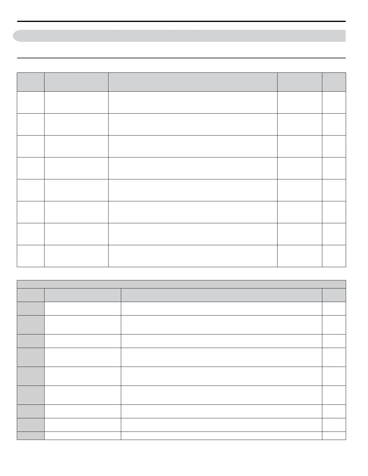
H1: Multi-Function Digital Inputs
No.
(Addr.
Hex)
Name Description Values Page
H1-01
(438)
Multi-Function Digital Input
Terminal S1 Function
Selection
Assigns a function to the multi-function digital inputs.
Refer to pages 454 to 456 for descriptions of setting values.
Note: Set unused terminals to F.
Default: 40 (F)
<1>
Min.: 1
Max.: 9F
205
H1-02
(439)
Multi-Function Digital Input
Terminal S2 Function
Selection
Assigns a function to the multi-function digital inputs.
Refer to pages 454 to 456 for descriptions of setting values.
Note: Set unused terminals to F.
Default: 41 (F)
<1>
Min.: 1
Max.: 9F
205
H1-03
(400)
Multi-Function Digital Input
Terminal S3 Function
Selection
Assigns a function to the multi-function digital inputs.
Refer to pages 454 to 456 for descriptions of setting values.
Note: Set unused terminals to F.
Default: 24
Min.: 0
Max.: 9F
205
H1-04
(401)
Multi-Function Digital Input
Terminal S4 Function
Selection
Assigns a function to the multi-function digital inputs.
Refer to pages 454 to 456 for descriptions of setting values.
Note: Set unused terminals to F.
Default: 14
Min.: 0
Max.: 9F
205
H1-05
(402)
Multi-Function Digital Input
Terminal S5 Function
Selection
Assigns a function to the multi-function digital inputs.
Refer to pages 454 to 456 for descriptions of setting values.
Note: Set unused terminals to F.
Default: 3 (0)
<1>
Min.: 0
Max.: 9F
205
H1-06
(403)
Multi-Function Digital Input
Terminal S6 Function
Selection
Assigns a function to the multi-function digital inputs.
Refer to pages 454 to 456 for descriptions of setting values.
Note: Set unused terminals to F.
Default: 4 (3)
<1>
Min.: 0
Max.: 9F
205
H1-07
(404)
Multi-Function Digital Input
Terminal S7 Function
Selection
Assigns a function to the multi-function digital inputs.
Refer to pages 454 to 456 for descriptions of setting values.
Note: Set unused terminals to F.
Default: 6 (4)
<1>
Min.: 0
Max.: 9F
205
H1-08
(405)
Multi-Function Digital Input
Terminal S8 Function
Selection
Assigns a function to the multi-function digital inputs.
Refer to pages 454 to 456 for descriptions of setting values.
Note: Set unused terminals to F.
Default: 8 (6)
<1>
Min.: 0
Max.: 9F
205
<1> Value in parenthesis is the default setting when a 3-Wire initialization is performed (A1-03 = 3330).
H1 Multi-Function Digital Input Selections
H1-oo
Setting
Function Description Page
0 3-Wire sequence
Closed: Reverse rotation (only if the drive is set up for 3-Wire sequence)
Terminals S1 and S2 are automatically set up for the Run command and Stop command.
206
1 LOCAL/REMOTE selection
Open: REMOTE (parameter settings determine the source of the frequency Reference 1 or 2
(b1-01, b1-02 or b1-15, b1-16)
Closed: LOCAL, Frequency reference and Run command are input from the digital operator.
206
2 External reference 1/2 selection
Open: Run command and frequency reference source 1 (determined by b1-01 and b1-02)
Closed: Run command and frequency reference source 2 (determined by b1-15 and b1-16)
207
3 Multi-Step Speed Reference 1
When input terminals are set to Multi-Step Speed References 1 through 3, switching
combinations of those terminals will create a multi-step speed sequence using the frequency
references set in d1-01 through d1-08.
207
4 Multi-Step Speed Reference 2
When input terminals are set to Multi-Step Speed References 1 through 3, switching
combinations of those terminals will create a multi-step speed sequence using the frequency
references set in d1-01 through d1-08.
207
5 Multi-Step Speed Reference 3
When input terminals are set to Multi-Step Speed References 1 through 3, switching
combinations of those terminals will create a multi-step speed sequence using the frequency
references set in d1-01 through d1-08.
207
6 Jog reference selection
Closed: Jog frequency reference (d1-17) selected. Jog has priority over all other reference
sources.
207
7 Accel/decel time selection 1
Used to switch between accel/decel time 1 (set in C1-01, C1-02) and accel/decel time 2 (set
in C1-03, C1-04).
207
8 Baseblock command (N.O.) Closed: No drive output 207
B.8 H Parameters: Multi-Function Terminals
454
YASKAWA SIEP YAIP1U 01C AC Drive - P1000 Technical Manual

 Loading...


