1.5 Component Names
This section gives an overview of the drive components and harmonic filter module components described in this manual.
Note: 1. Refer to Using the Digital Operator on page 109 for a description of the operator keypad.
2. The drive may have no cooling fans or up to two cooling fans depending on the model.
u
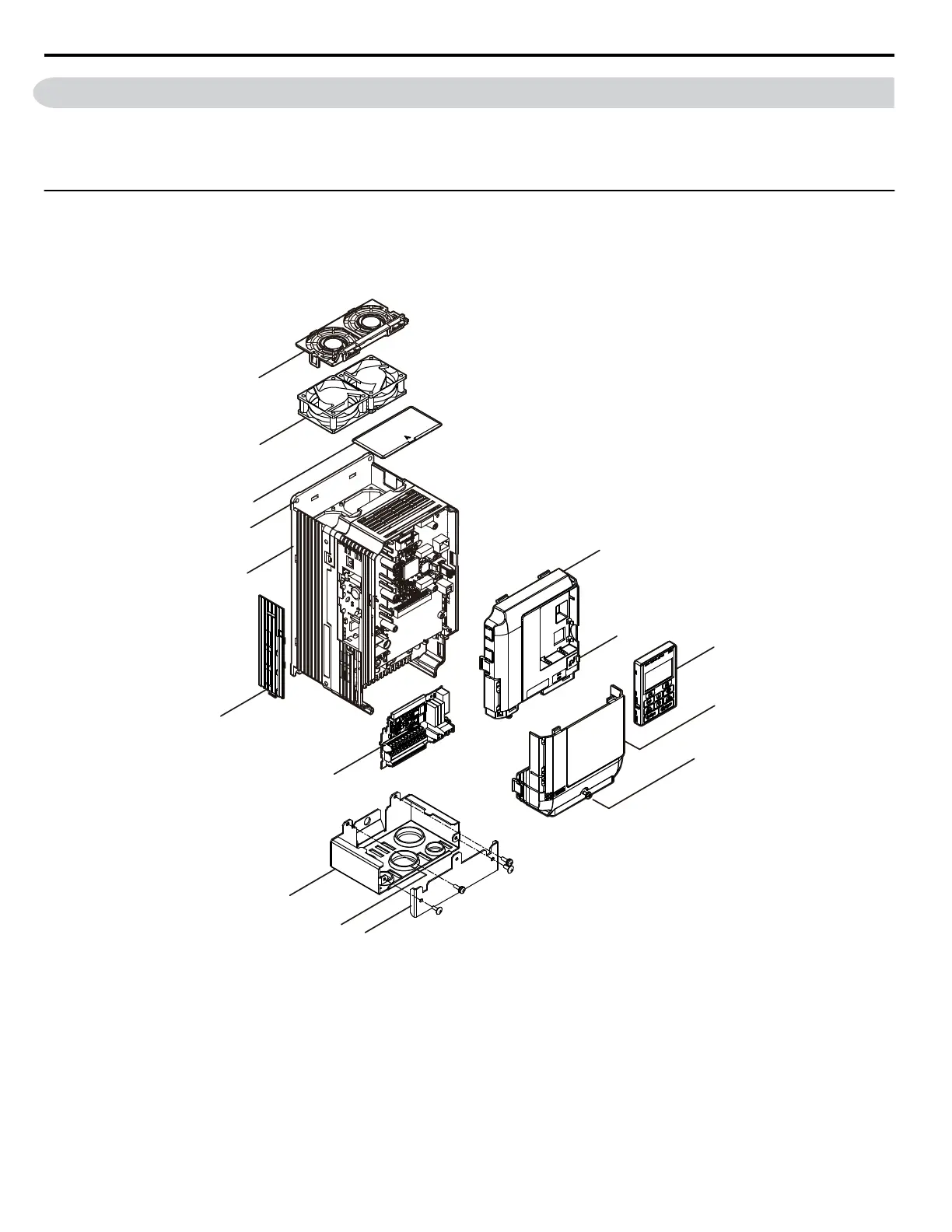
IP20/NEMA 1, UL Type 1 Enclosure
n
Three-Phase AC 200 V Models 2A0004F to 2A0081F
Three-Phase AC 400 V Models 4A0002F to 4A0044F
Three-Phase AC 600 V Models 5A0003F to 5A0032F
A – Front cover
B – USB port (type-B)
C – Digital operator
D – Terminal cover
E – Terminal cover screw
F – Conduit bracket front cover
G – Rubber bushing
H – Conduit bracket
I – Terminal board
J – Optional 24 V DC power supply
connector cover
K – Heatsink
L – Mounting hole
M – Top protective cover
N –
Cooling fan
<1>
O –
Fan finger guard
<1>
Figure 1.2 Exploded View of IP20/NEMA 1, UL Type 1 Components (Model 2A0030F)
<1> Drive models 2A0018, 2A0021, 4A0007 to 4A0011, 5A0006F, and 5A0009F have a single cooling fan. Drive models 2A0004
to 2A0012, 4A0002 to 4A0005, 5A0003F, and 5A0004F do not have a cooling fan or a fan finger guard.
1.5 Component Names
36
YASKAWA SIEP YAIP1U 01C AC Drive - P1000 Technical Manual

 Loading...


