Table 4.14 Auto-Tuning Input Data
Motor Type Auto-Tuning Type Digital Input Digital Output
IM Motor
Stationary Auto-Tuning for Line-to-Line Resistance
Digital input functions
are disabled.
Digital output functions are disabled.
Rotational Auto-Tuning for V/f Control Functions the same as during normal operation
n
Notes on Rotational Auto-Tuning
• Decouple the load from the motor to achieve optimal performance from Rotational Auto-Tuning. Rotational Auto-Tuning
is best suited for applications requiring high performance over a wide speed range.
• If it is not possible to decouple the motor and load, reduce the load so it is less than 30% of the rated load. Performing
Rotational Auto-Tuning with a higher load will set motor parameters incorrectly, and can cause irregular motor rotation.
• Ensure the motor-mounted brake is fully released, if installed.
• Connected machinery should be allowed to rotate the motor.
n
Notes on Stationary Auto-Tuning
Stationary Auto-Tuning modes analyze motor characteristics by injecting current into the motor for approximately one minute.
WARNING! Electrical Shock Hazard. When executing stationary Auto-Tuning, voltage is applied to the motor before the motor rotates. Do
not touch the motor until Auto-Tuning is completed. Failure to comply may result in injury or death from electrical shock.
WARNING! Sudden Movement Hazard. If installed, do not release the mechanical brake during Stationary Auto-Tuning. Inadvertent brake
release may cause damage to equipment or injury to personnel. Ensure that the mechanical brake release circuit is not controlled by the
drive multi-function digital outputs.
u
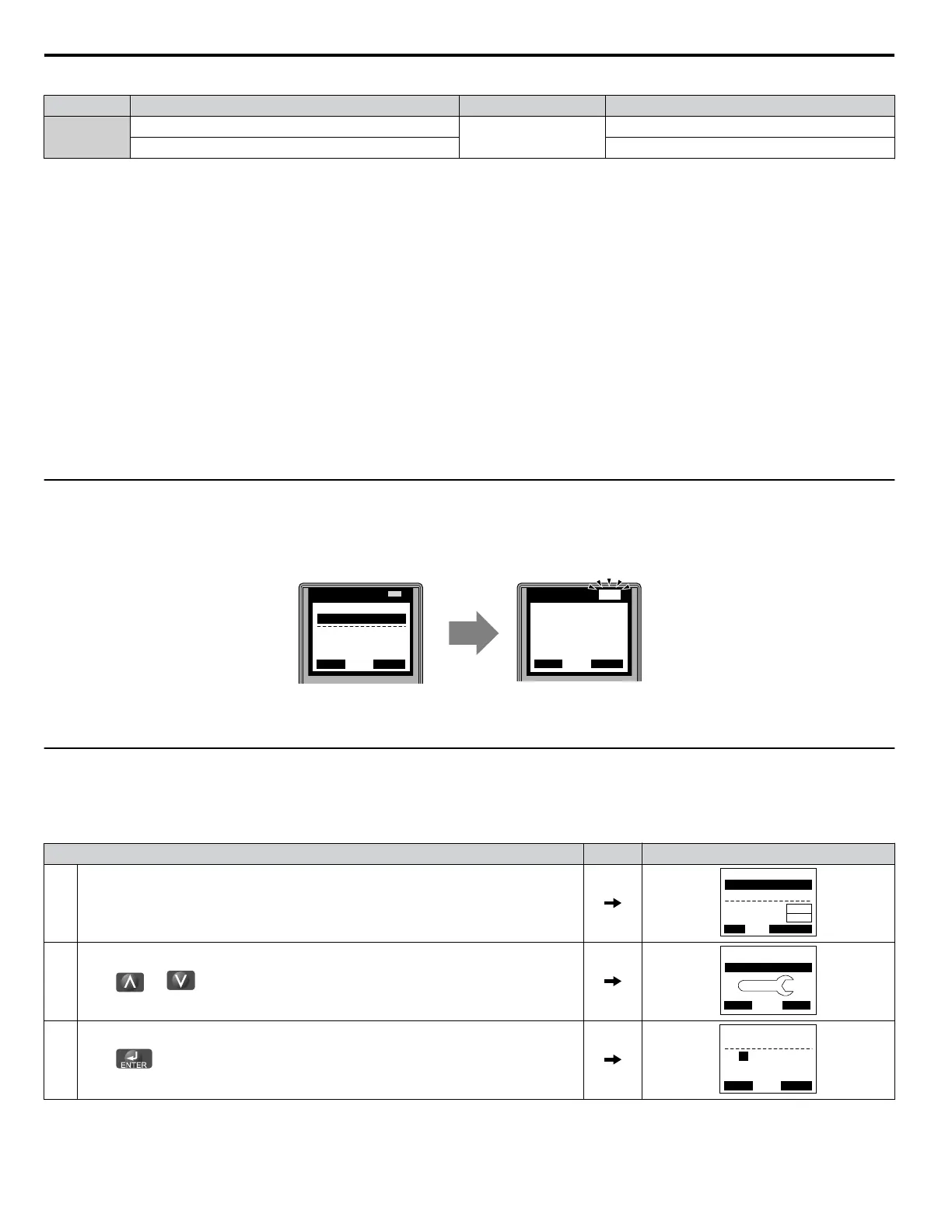
Auto-Tuning Interruption and Fault Codes
If tuning results are abnormal or the STOP key is pressed before completion, Auto-Tuning will be interrupted and a fault code
will appear on the digital operator.
LO
RE
ESC
RUN STOP
ENTERRESET
DIGITAL OPERATOR JVOP-180
LO
RE
ESC
RUN STOP
ENTERRESET
DIGITAL OPERATOR JVOP-180
ALM
ALM
- A.TUNE -
X.XX Hz/ X.XXA
DRV
Tune Proceeding
Rdy
FWD
<<<<<< >>> >>>
- MODE -
Er-03
STOP key
DRV
FWD
RESET
A – During Auto-Tuning
B – Auto-Tuning Aborted
Figure 4.10 Auto-Tuning Aborted Display
u
Auto-Tuning Operation Example
The following example demonstrates Stationary Auto-Tuning for Line-to-Line Resistance.
n
Selecting the Type of Auto-Tuning
Step Display/Result
1. Turn on the power to the drive. The initial display appears.
- MODE -
U1-01= 0.00Hz
U1-02= 0.00Hz
U1-03= 0.00A
DRV
FREF (OPR)
Rdy
JOG FWD FWD/REV
LSEQ
LREF
2.
Press or until the Auto-Tuning display appears.
HELP
- MODE - PRG
Auto-Tuning
DATA
AUTO
FWD
3.
Press to begin setting parameters.
- A.TUNE -
T1-01= 2 *2*
Term Resistance
PRG
Tuning Mode Sel
Rdy
ESC FWD DATA
4.7 Auto-Tuning
130
YASKAWA SIEP YAIP1U 01C AC Drive - P1000 Technical Manual

 Loading...


