6.9 Diagnosing and Resetting Faults
When a fault occurs and the drive stops, follow the instructions below to remove whatever conditions triggered the fault, then
restart the drive.
Note: An oC/SC fault will be displayed in the event of an IGBT failure. It may not be possible to reset this fault until the IGBT problem is corrected.
u
Fault Occurs Simultaneously with Power Loss
WARNING! Electrical Shock Hazard. Ensure there are no short circuits between the main circuit terminals (R/L1, S/L2, and T/L3) or between
the ground and main circuit terminals before restarting the drive. Failure to comply may result in serious injury or death and will cause
damage to equipment.
1.
Turn on the drive input power.
2.
Use monitor parameters U2-oo to display data on the operating status of the drive just before the fault occurred.
3.
Remove the cause of the fault and reset.
Note: 1. To find out what faults were triggered, check the fault history in U2-02. Information on drive status when the fault occurred
such as the frequency, current, and voltage can be found in U2-03 through U2-20. Refer to Viewing Fault Trace Data
After Fault on page 327 for information on how to view fault data.
2. When the fault continues to be displayed after cycling power, remove the cause of the fault and reset.
u
If the Drive Still has Power After a Fault Occurs
1.
Look at the digital operator for information on the fault that occurred.
2.
Refer to Fault Displays, Causes, and Possible Solutions on page 295.
3.
Reset the fault. Refer to Fault Reset Methods on page 328.
u
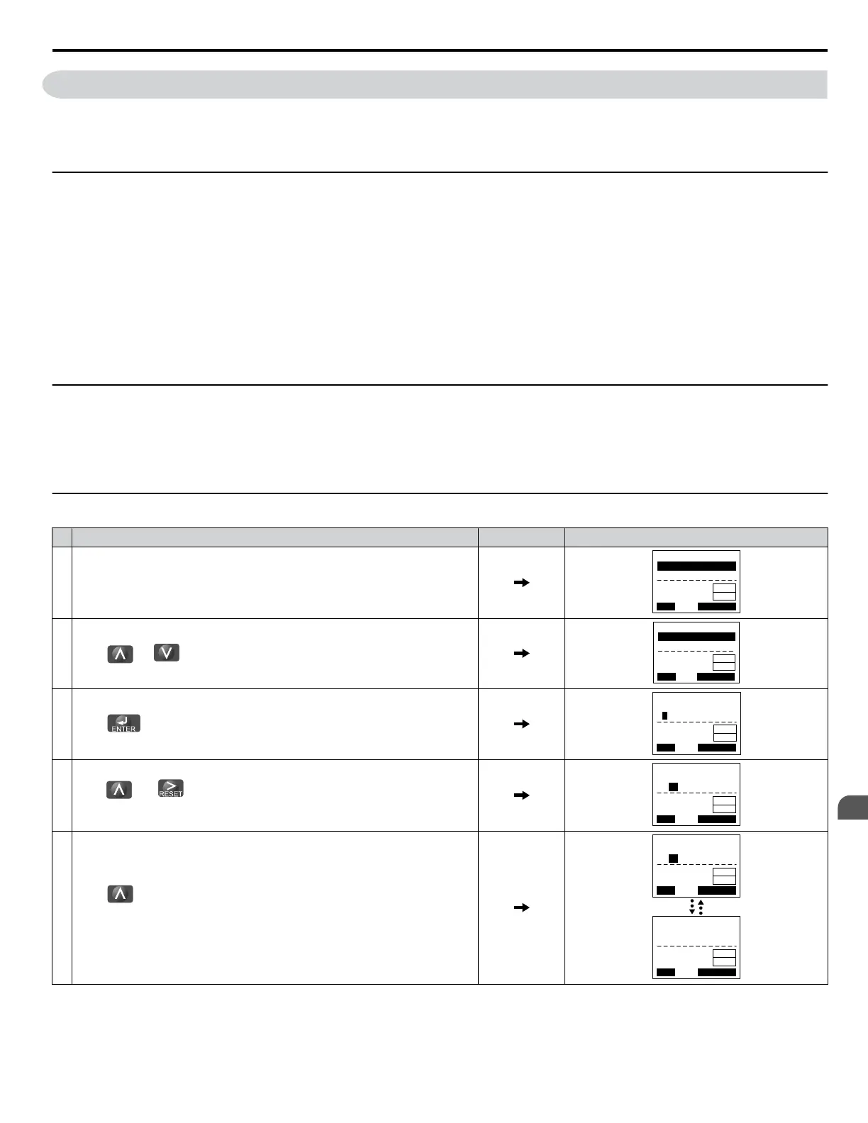
Viewing Fault Trace Data After Fault
Step Display/Result
1. Turn on the drive input power. The first screen displays.
- MODE -
U1-01= 0.00Hz
U1-02= 0.00Hz
U1-03= 0.00A
DRV
FREF (OPR)
Rdy
JOG FWD FWD/REV
LSEQ
LREF
2.
Press or until the monitor screen is displayed.
- MODE -
U1-01= 0.00Hz
U1-02= 0.00Hz
U1-03= 0.00A
DRV
Monitor Menu
Rdy
JOG FWD FWD/REV
LSEQ
LREF
3.
Press to display the parameter setting screen.
-MONITR-
U1 -01= 0.00Hz
U1-02= 0.00Hz
U1-03= 0.00A
DRV
Monitor
JOG FWD FWD/REV
Rdy
LSEQ
LREF
4.
Press and to scroll to monitor U2-02. The fault code shown in U2-02
is the fault that occurred most recently.
-
MONITR
-
U2-02= oC
U2-03= 0.00Hz
U2-04= 0.00Hz
DRV
Last Fault
Rdy
JOG FWD FWD/REV
LSEQ
LREF
5.
Press to view drive status information when fault occurred.
Parameters U2-03 through U2-20 help determine the cause of a fault.
Parameters to be monitored differ depending on the control mode.
-
MONITR
-
U2-03= 0.00Hz
U2-04= 0.00Hz
U2-05= 0.00A
DRV
Frequency Ref
Rdy
JOG FWD FWD/REV
LSEQ
LREF
-
MONITR
-
U2-20= XX °C
U2-01= -----
U2-02= -----
DRV
Heatsink Temp
Rdy
JOG FWD FWD/REV
LSEQ
LREF
6.9 Diagnosing and Resetting Faults
YASKAWA SIEP YAIP1U 01C AC Drive - P1000 Technical Manual
327
6
Troubleshooting

 Loading...


