3.9 Control Circuit Wiring
u
Control Circuit Connection Diagram
Refer to Figure 3.1 on page 69 when wiring terminals on the drive control circuit.
u
Control Circuit Terminal Block Functions
Drive parameters determine which functions apply to the multi-function digital inputs (S1 to S8), multi-function digital outputs
(M1 to M4), multi-function analog inputs (A1 to A3), and multi-function analog monitor output (FM, AM). The default setting
is listed next to each terminal in Figure 3.1 on page 69.
WARNING! Sudden Movement Hazard. Always check the operation and wiring of control circuits after being wired. Operating a drive with
untested control circuits could result in death or serious injury.
WARNING! Sudden Movement Hazard. Confirm the drive I/O signals and external sequence before starting test run. Setting parameter
A1-03 may change the I/O terminal function automatically from the factory setting. Failure to comply may result in death or serious injury.
n
Input Terminals
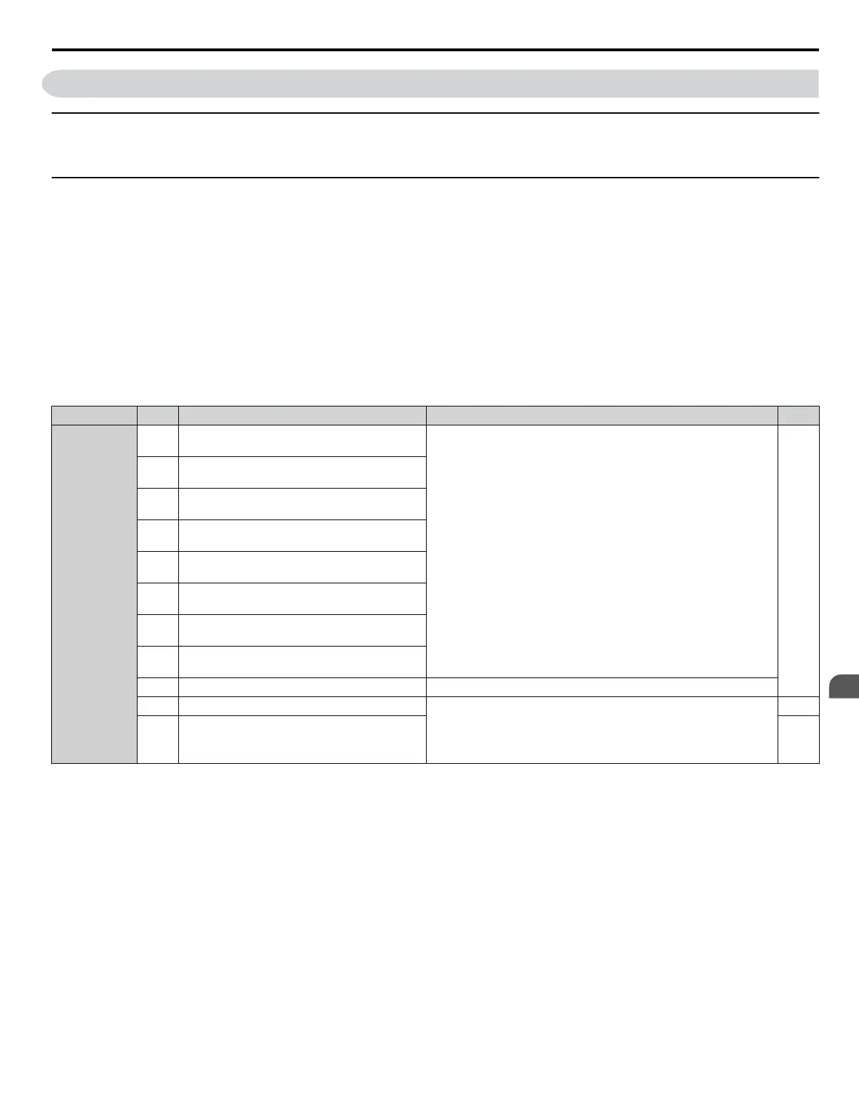
Table 3.7 lists the input terminals on the drive. Text in parenthesis indicates the default setting for each multi-function input.
Table 3.7 Control Circuit Input Terminals
Type No. Terminal Name (Function) Function (Signal Level) Default Setting Page
Multi-Function
Digital Inputs
S1
Multi-function input 1
(Closed: Forward run, Open: Stop)
• Photocoupler
• 24 Vdc, 8 mA
• Refer to Sinking/Sourcing Mode for Digital Inputs on page
101.
205
S2
Multi-function input 2
(Closed: Reverse run, Open: Stop)
S3
Multi-function input 3
(External fault, N.O.)
S4
Multi-function input 4
(Fault reset)
S5
Multi-function input 5
(Multi-step speed reference 1)
S6
Multi-function input 6
(Multi-step speed reference 2)
S7
Multi-function input 7
(Jog reference)
S8
Multi-function input 8
(Baseblock command (N.O.))
SC Multi-function input common Multi-function input common
SP Digital input power supply +24 Vdc 24 Vdc power supply for digital inputs, 150 mA max
NOTICE: Do not jumper or short terminals SP and SN. Failure
to comply will damage the drive.
101
SN
Digital input power supply 0 V
24 V transducer power supply 0 V
101
3.9 Control Circuit Wiring
YASKAWA SIEP YAIP1U 01C AC Drive - P1000 Technical Manual
95
3
Electrical Installation

 Loading...


