Type No. Terminal Name (Function) Function (Signal Level) Default Setting Page
Analog Inputs /
Pulse Train
Input
RP
Multi-function pulse train input
(Frequency reference)
• Input frequency range: 0 to 32 kHz
• Signal Duty Cycle: 30 to 70%
• High level: 3.5 to 13.2 Vdc, low level: 0.0 to 0.8 Vdc
• Input impedance: 3 kΩ
148
232
+V Power supply for analog inputs 10.5 Vdc (max allowable current 20 mA) 147
24 V
+24 Vdc transducer power supply for customer
use
150 mA maximum capacity –
A1
Multi-function analog input 1
(Frequency reference bias)
• -10 to 10 Vdc, 0 to 10 Vdc (input impedance: 20 kΩ)
• 4 to 20 mA, 0 to 20 mA (input impedance: 250 Ω)
• Voltage or current input must be selected by jumper S1 and H3-01.
147
225
A2
Multi-function analog input 2
(Frequency reference bias)
• -10 to 10 Vdc, 0 to 10 Vdc (input impedance: 20 kΩ)
• 4 to 20 mA, 0 to 20 mA (input impedance: 250 Ω)
• Voltage or current input must be selected by jumper S1 and H3-09.
147
147
226
A3
Multi-function analog input 3
(Frequency reference bias)
• -10 to 10 Vdc, 0 to 10 Vdc (input impedance: 20 kΩ)
• 4 to 20 mA, 0 to 20 mA (input impedance: 250 Ω)
• Voltage or current input must be selected by jumper S1 and H3-05.
147
AC Frequency reference common 0 V 147
E (G) Ground for shielded lines and option cards – –
n
Output Terminals
Table 3.8 lists the output terminals on the drive. Text in parenthesis indicates the default setting for each multi-function output.
Table 3.8 Control Circuit Output Terminals
Type No. Terminal Name (Function) Function (Signal Level) Default Setting Page
Fault Relay
Output
MA N.O.
30 Vdc, 10 mA to 1 A; 250 Vac, 10 mA to 1 A
Minimum load: 5 Vdc, 10 mA
215MB N.C. output
MC Fault output common
Multi-Function
Digital Output
<1>
MD N.O.
30 Vdc, 10 mA to 1 A; 250 Vac, 10 mA to 1 A
Minimum load: 5 Vdc, 10 mA
215
ME N.C. Output
MF Common (Speed agree)
M1
Multi-function digital output (During run)
30 Vdc, 10 mA to 1 A; 250 Vac, 10 mA to 1 A
Minimum load: 5 Vdc, 10 mA
M2
M3
Multi-function digital output (Zero speed)
M4
Monitor
Output
FM Analog monitor output 1 (Output frequency)
-10 to +10 Vdc, or 0 to +10 Vdc 230
AM Analog monitor output 2 (Output current)
AC Monitor common 0 V –
<1> Refrain from assigning functions to digital relay outputs that involve frequent switching, as doing so may shorten relay performance life. Switching
life is estimated at 200,000 times (assumes 1 A, resistive load).
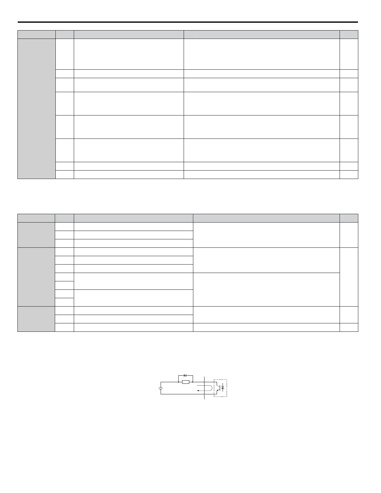
Connect a suppression diode as shown in Figure 3.30 when driving a reactive load such as a relay coil. Ensure the diode rating
is greater than the circuit voltage.
A
B
C
D
A – External power, 48 V max.
B – Suppression diode
C – Coil
D – 50 mA or less
Figure 3.30 Connecting a Suppression Diode
3.9 Control Circuit Wiring
96
YASKAWA SIEP YAIP1U 01C AC Drive - P1000 Technical Manual

 Loading...


