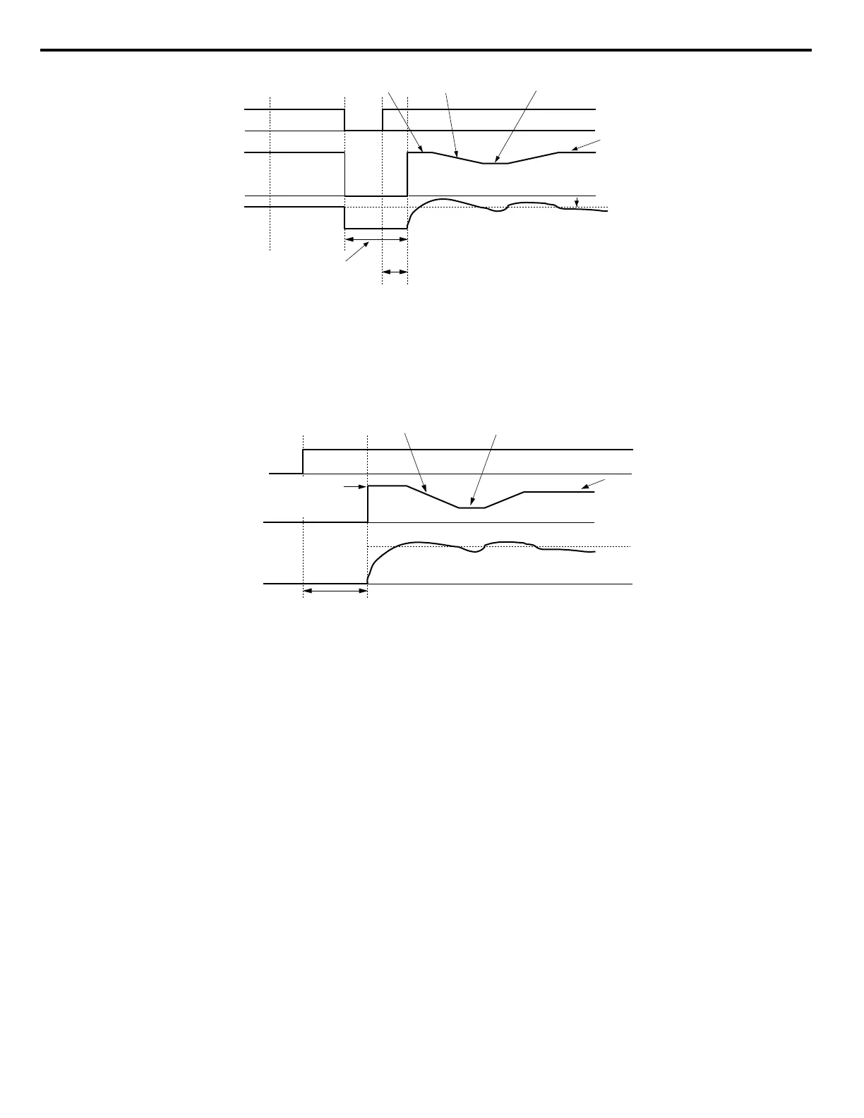
AC power
supply
Output
frequency
Output
current
OFFON
Output frequency before
momentary power loss
Selected
frequency
reference
Min. Baseblock Time (L2-03)
Decel time
set to b3-03
Waits for twice
as long as L2-04
Speed Search operation
current set to b3-02
b3-05
Figure 5.9 Current Detection Speed Search after Power Loss
Note: After power is restored, the drive waits until the time set to b3-05 has passed before performing Speed Search. Thereby the Speed Search
may start not at the end of L2-03 but even later.
When Speed Search is applied automatically with the Run command, the drive waits for the minimum baseblock time set to
L2-03 before starting Speed Search. If L2-03 is lower than the time set to parameter b3-05, then b3-05 is used as the wait time.
Run command
Output
frequency
Output current
OFF ON
b3-02
Decel time set
set to b3-03
Waits for twice
as long as L2-04
Selected
frequency
reference
Minimum Baseblock Time (L2-03)
Max. output frequency
or the specified
frequency reference
Figure 5.10 Current Detection Speed Search at Start or Speed Search Command by Digital Input
Notes on Using Current Detection Type Speed Search
• Shorten the Speed Search deceleration time set to b3-03 if an oL1 fault occurs while performing Current Detection Speed
Search.
• Increase the minimum baseblock time set to L2-03 if an overcurrent or overvoltage fault occurs when performing Speed
Search after power is restored following a momentary power loss.
n
Speed Estimation Type Speed Search (b3-24 = 1)
This method can be used for a single induction motor connected to a drive. Do not use this method if the motor is one or more
frame size smaller than the drive, at motor speeds above 200 Hz, or when using a single drive to operate more than one motor.
Speed Estimation is executed in the two steps described below:
Step 1: Back EMF Voltage Estimation
This method is used by Speed Search after baseblock (e.g., a power loss where the drive CPU continued to run and the Run
command was kept active). Here, the drive estimates the motor speed by analyzing the back EMF voltage and outputs the
estimated frequency and increases the voltage using the time constant set in parameter L2-04. After that, the motor is accelerated
or decelerated to the frequency reference starting from the detected speed. If there is not enough residual voltage in the motor
windings to perform the calculations described above, the drive will automatically proceed to step 2.
5.2 b: Application
154
YASKAWA SIEP YAIP1U 01C AC Drive - P1000 Technical Manual

 Loading...


