Setting Function
1E Restart Enabled 222
1F Motor Overload Alarm (oL1) 222
20 Drive Overheat Pre-Alarm (oH) 222
22 Mechanical Weakening Detection 222
2F Maintenance Period 222
37 During Frequency Output 222
38 Drive Enabled 223
39 Watt Hour Pulse Output 223
3C LOCAL/REMOTE Status 223
3D During Speed Search 223
3E PID Feedback Low 223
3F PID Feedback High 223
4A During KEB Operation 223
4C During Fast Stop 223
Setting Function
4D oH Pre-Alarm Time Limit 223
4E
<2>
Braking Transistor Fault (rr) 223
4F
<2>
Braking Resistor Overheat (rH) 223
50 Waiting to Run 223
51 Sequence timer 1 224
52 Sequence timer 2 224
53 Sequence timer 3 224
54 Sequence timer 4 224
58 UL6 Detected 224
60 Internal Cooling Fan Alarm 223
71 Secondary PI Feedback Low 224
72 Secondary PI Feedback High 224
100 to 192 Functions 0 to 92 with Inverse Output 224
<2> Not available in models 2A0169 to 2A0415 and 4A0088 to 4A1200.
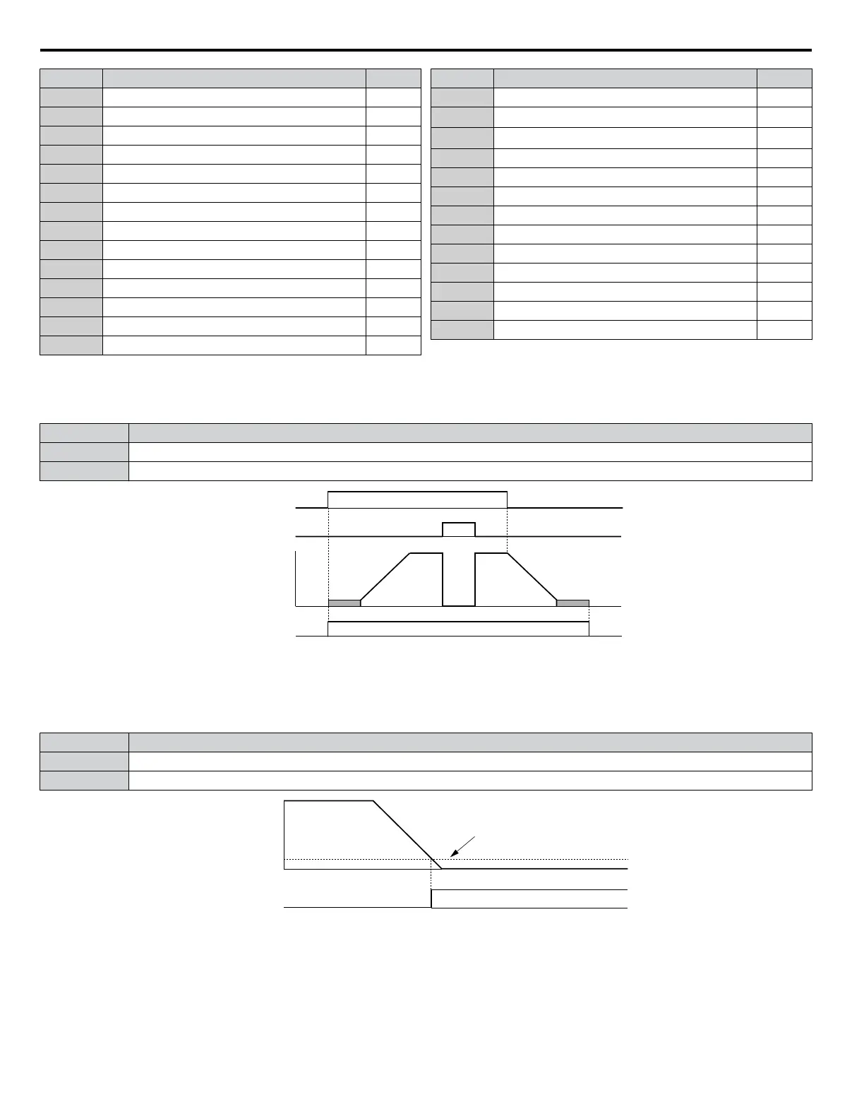
Setting 0: During Run
Output closes when the drive is outputting a voltage.
Status Description
Open Drive is stopped.
Closed A Run command is input or the drive is in deceleration or DC injection.
ON
ON
OFF
OFF
ONOFF
Run command
Baseblock
command
Output
frequency
During Run
Figure 5.45 During Run Time Chart
Setting 1: Zero Speed
Terminal closes when the output frequency falls below the minimum output frequency set to E1-09 or b2-01.
Status Description
Open Output frequency is above the minimum output frequency set to E1-09 or b2-01
Closed Output frequency is less than the minimum output frequency set to E1-09 or b2-01
OFF
Output frequency
Zero Speed
ON
E1-09 (Min. Output Frequency) or
b2-01 (Zero Speed Level)
Figure 5.46 Zero-Speed Time Chart
Setting 2: Speed Agree 1 (f
ref
/f
out
Agree 1)
Closes when the actual output frequency is within the Speed Agree Width (L4-02) of the current frequency reference regardless
of the direction.
5.7 H: Terminal Functions
216
YASKAWA SIEP YAIP1U 01C AC Drive - P1000 Technical Manual

 Loading...


