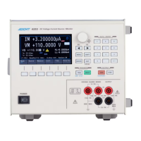
The 6253 is a DC Voltage Current Source/Monitor designed for high-sensitivity measurements and various sourcing functions, including pulse and sweep modes. It offers 5½-digit source resolution and 6½-digit measurement resolution, making it suitable for evaluating semiconductors and electronic components in research, development, and characteristic evaluation systems.
Function Description
The 6253 operates in several source modes:
- DC Source Mode: Generates stable DC voltage or current.
- Pulse Source Mode: Generates pulse voltage or current with a minimum pulse width of 25 µs.
- DC Sweep Source Mode: Generates staircase waveforms for DC voltage or current sweeps, supporting linear, fixed, random, multi-slope linear, and log sweep functions.
- Pulse Sweep Source Mode: Generates pulse staircase waveforms for pulse voltage or current sweeps, also supporting linear, fixed, random, multi-slope linear, and log sweep functions.
The device offers comprehensive measurement capabilities:
- Voltage Source Current Measurement (VSIM): Measures current while sourcing voltage.
- Current Source Voltage Measurement (ISVM): Measures voltage while sourcing current.
- Voltage Source Voltage Measurement (VSVM): Monitors the sourced voltage.
- Current Source Current Measurement (ISIM): Monitors the sourced current.
- Resistance Measurement (RM): Calculates resistance by dividing voltage by current.
Key operational features include:
- Numerical Input: Values can be set using a rotary knob with right/left keys for fine adjustment or through a direct input mode using a numeric keypad.
- Soft Keys: Context-sensitive soft keys on the color display provide quick access to mode selection, source and measurement condition settings, limit values, and time parameters.
- MENU Hierarchy: A two-layer menu structure allows for detailed parameter configuration.
- Trigger Modes: Supports AUTO and HOLD trigger modes for measurements and sweep operations.
- Output Status: The device can be in Operate (output ON), Standby (output OFF, relays disconnected), or Suspend (output ON, but with Vsus voltage and high/low impedance settings) status. The Suspend function is recommended to extend relay life.
- Limit (Compliance) Function: Allows setting high (HL) and low (LL) limit values for voltage or current to protect the Device Under Test (DUT) from over-voltage or over-current. Limits can be set in
±Balance (symmetrical) or Individual (asymmetrical) modes.
- Calculation Functions: Includes NULL calculation (to cancel leak current or offset values), Scaling calculation (to apply a linear transformation to measured data), Comparator calculation (to compare measured values against set limits), and Max/Min calculation (to determine maximum, minimum, average, and total measured values).
- Measurement Data Memory: Stores up to 20,000 measurement data items in Normal or Burst mode. Data can be viewed graphically.
- Auto Zero Function: Periodically measures and cancels offset drift of the AD converter, improving measurement accuracy.
- Variable Slew Rate: Allows setting rise and fall times for voltage source output, with automatic adjustment of output response based on the slew rate range.
- Remote Sensing (2-Wire/4-Wire Connection): Supports both 2-wire and 4-wire connections to compensate for voltage drops across cables, especially important for high current measurements or when cable resistance matters.
- External Control Signals: Features TRIGGER IN, SYNC OUT, COMPLETE OUT, BUSY IN/OUT, INTERLOCK IN, STBY IN, OPR/SBY IN, OPR/SUS IN, and OPERATE OUT for synchronous operation with multiple units and control of external devices.
- Multiple Unit Operation: Supports synchronous, serial, and parallel connections of multiple 6253 units for expanded capabilities.
- Error Log: Stores up to five error messages, which can be viewed to diagnose problems.
Important Technical Specifications
- Source/Measurement Ranges:
- Voltage: 300 mV to 100 V (±2 A at ±32 V, ±1 A at ±64 V, ±0.5 A at ±110 V).
- Current: 3 µA to 2 A.
- Resolution:
- Voltage Source: 5 µV.
- Voltage Measurement: 100 nV.
- Current Source: 50 pA.
- Current Measurement: 1 pA.
- Display Digits: Source: 5½ digits, Measurement: 6½ digits.
- Minimum Pulse Width: 25 µs.
- Output: Sink-enabled bipolar output.
- Interfaces: USB and GPIB are standard. LAN and RS232 are available as factory options.
- Power Supply: AC power 100 V, 120 V, 220 V, 240 V (user selectable).
- Power Consumption: 330 VA or less.
- Dimensions: Approx. 212 (W) × 177 (H) × 450 (D) mm.
- Mass: 15 kg or less.
- Safety: Compliant with IEC61010-1 Ed.3.
- EMC: Compliant with EN61326-1 classA.
- Vibration Proof: Compliant with IEC60068-2-6, 2G.
- Operating Environment:
- Temperature: 0 °C to +50 °C (operation), -25 °C to +70 °C (storage).
- Humidity: 85% RH or lower (without condensation).
- Indoor use, free from corrosive gases, direct sunlight, dust, vibration, and excessive noise.
- Warm-up Time: At least 60 minutes for specified accuracy.
- Calibration Interval: Recommended once a year.
Usage Features
- Color Display: Enhances operability and data visualization.
- Numeric Keypad: Facilitates direct and quick input of numerical values.
- Graph Display: Allows visual analysis of measurement data stored in memory, with cursor and zoom functions.
- Interlock Function: For safety, the device can be connected to a fixture (e.g., 12701A) to automatically set to Standby if the fixture cover opens.
- Remote Control: Full control via USB, GPIB, LAN, or RS232 interfaces, enabling integration into automated measurement systems. Sample programs are available for download.
Maintenance Features
- Self-Test: Performs internal checks upon power-on or manually, displaying error codes for diagnosis.
- Life-Limited Parts: Key components such as the unit power supply, fan motor, electrolytic capacitor, LCD display, LCD backlight, memory backup battery, operate/standby relay, panel keys, USB/GPIB/LAN/RS232 connectors, and rotary knob have specified expected lifespans. Users are advised to contact ADC for replacement services.
- Disposal and Recycling: Instructions are provided for proper disposal of harmful substances in accordance with local and national regulations.
- Troubleshooting Guide: An appendix lists common problems, their causes, and solutions to assist users before requesting repairs.