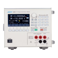
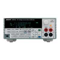
6253 DC Voltage Current Source/Monitor Operation Manual
4.2.10 External Control Signals
4-61
4.2.10 External Control Signals
The external control signals are used to synchronize multiple units and control external devices such as
scanners and digital multimeters.
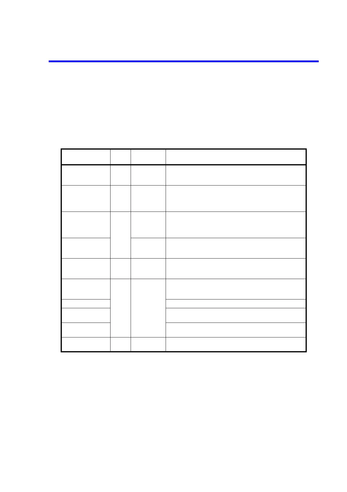
The following table shows the signal names, their levels and functions.
Table 4-12 External Control Signal Functions
Signal
Input/
output
Level Description
TRIGGER IN Input TTL negative
pulse
(2 s or more)
• Measurement start for the DC source mode
• Pulse output for the pulse source mode
• Start or step-up for the sweep source mode
SYNC OUT Output TTL negative
pulse
(10 s or more)
*3
• Period start signal for the DC source mode
• Pulse output signal for the pulse source mode
• Step-up signal for the sweep source mode
COMPLETE OUT *1 Output TTL negative
pulse
(10 s or more)
*3
• Measurement start signal (Meas Front) *4
• Measurement complete and period complete signal (Meas End) *4
• Comparator calculation result signal (CMP HI/GO/LO) *4
• Sweep end or stop signal (Sweep end)
BUSY OUT *1 TTL negative
level
• Operating signal output
(“LO” is output from the source start until the measurement end and
period end)
BUSY IN *1 Input TTL negative
level
• Operating signal input *4
(The step operation for measurement or sweep is not performed
when the input signal is “LO.”)
INTERLOCK *2 Input TTL negative
level
• Sets Standby when the signal level changes from LO to HI.
• When the signal is “HI” or the input is open, the output cannot be
changed to Operate.
STBY IN *2 • Sets Standby when the signal level changes from LO to HI.
OPR/SBY IN *2 • Sets Standby when the signal level changes from LO to HI.
• Sets Operate when the signal level changes from HI to LO.
OPR/SUS IN *2 • Sets Suspend when the signal level changes from LO to HI.
• Sets Operate when the signal level changes from HI to LO.
OPERATE OUT *2 Output TTL negative
level
• Outputs LO in the Operate status.
• Outputs HI in the Standby or Suspend status.
*1, *2: The same terminal is used by switching respectively.
*3: The output signal pulse width can be switched to 100 s.
*4: Invalid when the measurement data memory is set to Burst