Do you have a question about the ADCMT 6241A and is the answer not in the manual?
Explains the meaning of danger, warning, and caution symbols used.
Lists essential safety precautions for operating the instrument.
Details caution symbols and their meanings within the manual.
Describes safety marks found on the product itself.
Discusses parts with limited lifespan and their replacement.
Provides operational warnings for products with hard disks.
Advises on the proper disposal of the instrument and its harmful substances.
Specifies the correct operating position for the instrument.
Details the correct storage position for the instrument.
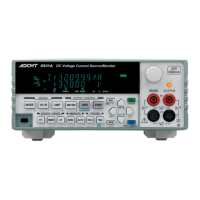
Provides a general description of the 6241A/6242 DC Voltage Current Source/Monitor.
Details the required ambient temperature, humidity, and location conditions for operation.
Advises on proper placement, ventilation, and spacing for the instrument.
Provides guidelines for installing the instrument in a rack.
Provides instructions for cleaning the instrument's exterior.
Details the recommended storage conditions and procedures.
Outlines the proper packing procedures for transporting the instrument.
Describes the part names and functions of the front and rear panels and screen display.
Details the fluorescent character display tube and its functions.
Describes the MODE, VS/IS, and LIMIT keys in the SOURCE section.
Explains the FIT, DOWN, and UP keys for source range selection.
Describes the MON and AUTO keys for measurement function and range selection.
Explains the 4W/2W, OPR, SUSPEND, and STBY keys.
Details the HOLD, TRIG, and SWP STOP keys for trigger and sweep control.
Describes various other keys like MENU, NULL, 123, cursor keys, SHIFT, EXIT, LOCAL.
Explains the OUTPUT and SENSE terminals and the OUTPUT Indicator.
Describes the function of the POWER switch.
Lists and explains the status indicators like PLS, SWP, DC, HOLD, AUTO, 4W, 2W, MATH, AZ, NULL, ST.
Explains the blinking auxiliary indicator for menu navigation.
Describes the FIT indicator for source range setting.
Explains the indicator for 500 mA/5 A current source or limiter range.
Describes FAST and SLOW indicators for output response.
Explains the HL and LL indicators for limiter status.
Explains the TpALM indicator related to period time.
Details right status indicators like RMT, MA, SRQ, ERR, CAL, OPR, LMT, OSC, RVS, BUSY, SHIFT.
Explains the INTERLOCK, OPERATE IN, and OPERATE OUT signals.
Describes the port for connecting GPIB cable.
Describes the port for connecting USB cable.
Details how to set the source value using various keys.
Illustrates the relationship between keys for setting source value.
Explains setting source value using cursor keys or rotary knob when FIT is OFF.
Describes how to change the source range using UP/DOWN keys.
Explains setting source value using cursor keys or rotary knob when FIT is ON.
Details how to set source value using direct input mode with numeric keys.
Describes how to set limiter values using the ± Balance setting.
Explains how to set limiter values separately for HL and LL.
Details setting the same polarity for HL and LL values.
Explains the procedure for operating the hierarchical menus.
Lists parameters related to the SOURCE category in the menu.
Lists parameters related to the SWEEP category in the menu.
Details parameters for SWEEP VAL category, including linear, fixed, and random sweep types.
Lists parameters related to timing settings like Hold Time, Src Delay, Meas Delay.
Lists parameters for measurement settings like Auto Zero, Integ Time, Measure SW.
Details parameters for measurement data memory like Store Mode, Mem Recall, Mem Clear.
Covers parameters for random memory data set, save, and clear.
Lists parameters for computation functions like Comparator, Scaling, Max/Min.
Details constants for calculations like High Value, Low Value, SCL Val.
Describes external control signal settings like OPR Signal, Cmpl/Sync, Sig Width.
Covers parameters for loading and saving settings like Parm Load, Parm Save, PON. Load.
Details interface settings for GPIB and USB, including address and talk mode.
Lists system parameters like Limit Buz, Compare Buz, Notice Buz, Self Test, Error Log.
Describes the steps needed before performing DC measurement.
Explains the voltage source measurement (VSIM) operation and display.
Explains the current-source measurement (ISVM) operation.
Outlines preparation steps for pulse measurement.
Details how to set the pulse source value.
Explains how to set the current-limiter value.
Describes how to set the base value for pulse measurement.
Details how to set pulse time parameters like Tds, Tw, Tp.
Outlines preparation steps for sweep measurement.
Details how to set the current-limiter for sweep measurement.
Explains how to set the sweep source mode (DC Sweep, Pulse Sweep).
Details how to set the start, stop, and step values for sweep.
Describes how to set sweep time parameters like Src Delay, Meas Delay, Period.
Explains how to set the measurement data memory (Store Mode).
Shows the relationships between source modes, functions, and setting parameters.
Lists restrictions when changing the source function during operation.
Explains how the unit outputs source values based on range settings.
Details the auto range levels for 6241A and 6242.
Discusses how range changes during sweep affect period time.
Details the instrument's operational status transitions (Standby, Suspend, Operate).
Explains how to set suspend voltage and its relation to source range.
Describes how to set output resistance (HiZ, LoZ) in Suspend mode.
Illustrates status transitions between Operate, Standby, and Suspend.
Lists available measurement functions (Voltage, Current, Resistance) and linking modes.
Shows the upper and lower range levels for measurement auto range.
Explains auto range operation with DC source mode using diagram examples.
Specifies the conditions and restrictions for setting limiter values.
Explains setting types (±Balance, Separate) and their operations for limiters.
Describes how limiters are detected and indicated via LMT, HL, LL.
Lists alarm conditions, messages, descriptions, and causes.
Details the restrictions when setting time parameters in relation to each other.
Shows how time parameter restrictions apply across different source modes.
Explains how set time resolutions are determined by period time resolution.
Describes settling time and measurement delay settings.
Provides formulas and tables for calculating settling time for voltage-source.
Provides formulas and tables for calculating settling time for current-source.
Explains the NULL calculation for canceling leak current or offset value.
Details the scaling calculation formula and operation.
Explains the comparator calculation results and outputting.
Describes how Max/Min calculation determines maximum, minimum, average, and total values.
Outlines restrictions for using the external trigger signal.
Explains synchronized operation of multiple units using external control signals.
Explains how measured data is stored in Normal and Burst modes.
Details the conditions under which saved data can be cleared.
Explains how to use GPIB or USB interfaces for external control.
Details how to select the interface (GPIB/USB) and set related parameters.
Provides an overview of the GPIB interface and its capabilities.
Provides an overview of the USB interface and its specifications.
Lists the standard, connectors, identifier ID, and commands for the USB interface.
Guides on setting up the USB connection to a PC.
Details how to set the unique USB ID for instruments.
Advises on precautions when running query commands via USB.
Explains the hierarchical status register model with Event and Enable Registers.
Describes how to enable bits in Event Registers using decimal values.
Explains the Status Byte Register and its summary function.
Details the functions assigned to the Standard Event Status Register.
Describes the main and sub headers in the data output format.
Details the mantissa and exponent parts for unit display and scaling calculation.
Explains the output of the comma "" as a string delimiter.
Describes block delimiters and commands to specify them.
Defines the syntax for remote commands, including header, spaces, data, and multiple commands.
Covers parameters for saving and initializing settings like STP0, SINI, RCLP.
Explains commands for initializing the instrument, like *RST and C.
Describes the *IDN? command for querying instrument information.
Covers automatic setting for electrical frequency.
Explains settings for the notice buzzer.
Details settings for the comparator calculation result buzzer (BZ0-BZ4).
Explains settings for the limit detection buzzer (UZ0, UZ1).
Describes how to execute and read self-test results (*TST?, TER?).
Explains how to read and clear error logs (ERL?, ERC?).
Details commands for interlock signal input/output (OP0-OP4).
Covers CP and CW commands for synchronous control signals.
Explains commands for setting GPIB block delimiters (DL0-DL3).
Describes commands for header output (OH0, OH1).
Details the calibration procedure using commands like CAL0, CAL1, XINI, XWR.
Explains commands for handling calibration data like XINI, XWR.
Lists commands for selecting calibration modes (XVS, XIS, XVLH, etc.).
Details commands for setting calibration ranges (XR-1 to XR5).
Explains commands for inputting DMM data and adjusting calibration (XDAT, XD, XADJ, XUP, XDN, XNXT).
Introduces programming examples for operating the instrument via GPIB.
Provides a VBA code example for performing DC measurement via GPIB.
Provides a VBA code example for performing sweep measurement via GPIB.
Provides a VBA code example for performing DC measurement via USB.
Outlines the methods for checking the 6241A's performance and accuracy.
Lists the measuring instruments needed for performance tests.
Describes the connections required for performance tests.
Details the conditions and procedures for executing performance tests.
Explains the procedure for testing voltage source measurement accuracy.
Details the procedure for testing current source measurement accuracy.
Details testing 6242 current source measurement accuracy for 3 A and 5 A ranges.
Lists the measuring instruments needed for 6242 performance tests.
Describes the connections required for 6242 performance tests.
Details the conditions and procedures for executing 6242 performance tests.
Explains the procedure for testing 6242 voltage source measurement accuracy.
Details testing 6242 current source measurement accuracy.
Details testing 6242 current source measurement accuracy for 3 A and 5 A ranges.
Details the calibration procedure for the 6241A model.
Lists the necessary cables and instruments for calibration.
Provides safety precautions to be followed before and during calibration.
Shows the connection diagrams for calibrating the 6241A using the 6581.
Lists calibration points and tolerance ranges for the 6241A.
Outlines the general steps for calibrating the 6241A using remote commands.
Details the calibration procedure for voltage source and limiter.
Explains the calibration procedure for voltage measurement.
Details calibration for current source and limiter in the specified range.
Details calibration for current source and limiter in 3 A and 5 A ranges.
Explains calibration for current measurement in the specified range.
Explains calibration for current measurement in 3 A and 5 A ranges.
Lists cables and instruments for 6242 calibration.
Provides safety precautions for calibration.
Shows connection diagrams for 6242 calibration using 6581.
Lists calibration points and tolerance ranges for the 6242 model.
Outlines the general steps for calibrating the 6242 using remote commands.
Details the calibration procedure for voltage source and limiter.
Explains the calibration procedure for voltage measurement.
Details calibration for current source and limiter in the specified range.
Details calibration for current source and limiter in 3 A and 5 A ranges.
Explains calibration for current measurement in the specified range.
Explains calibration for current measurement in 3 A and 5 A ranges.
Lists specifications for source and measurement functions.
Details the source and measurement specifications for the 6241A model.
Details the source and measurement specifications for the 6242 model.
Lists typical execution times for GPIB/USB remote commands.