6241A/6242 DC Voltage Current Source/Monitor Operation Manual
6.5 Status Register Structure
6-17
6. Error Register
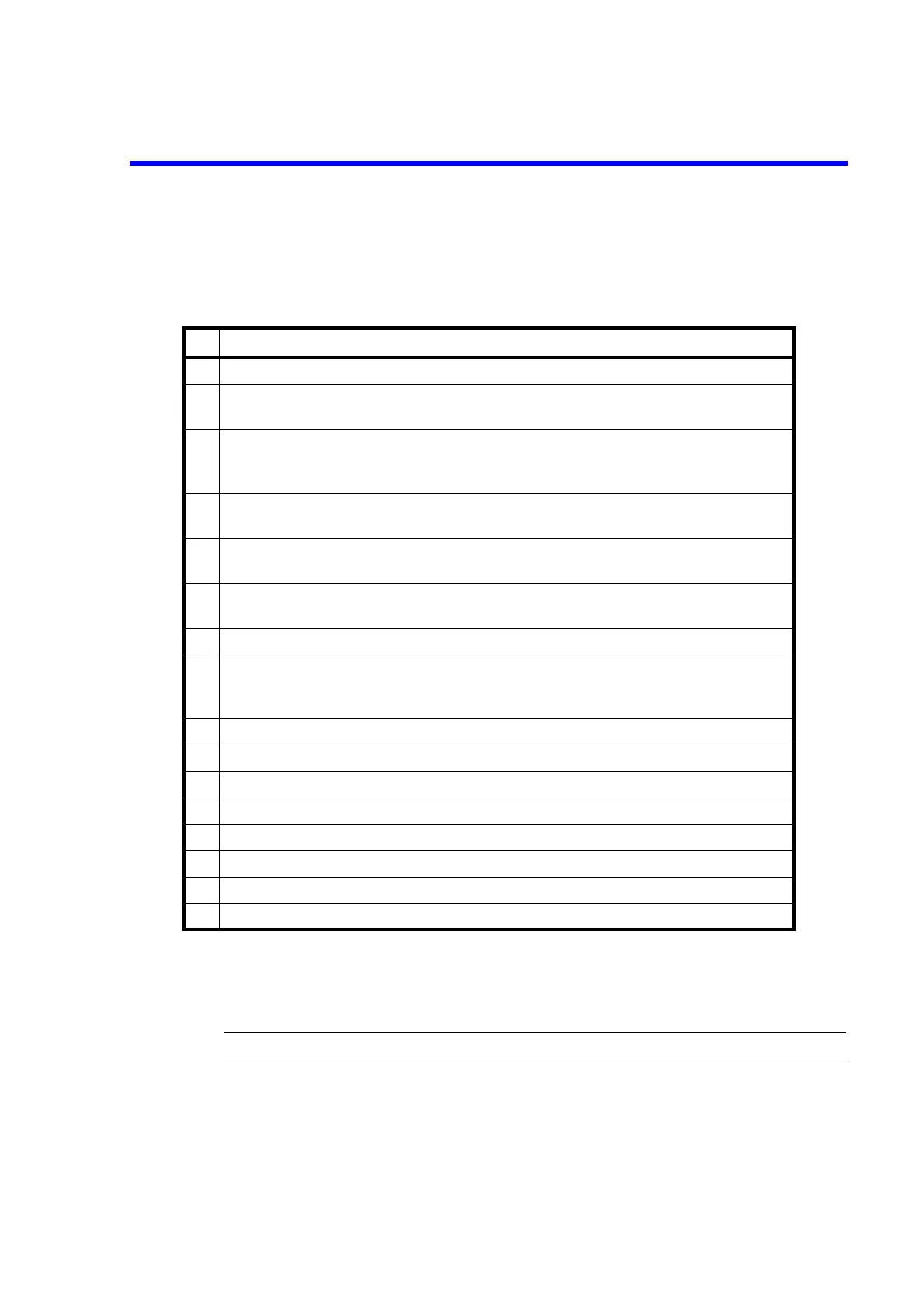
Table 6-6 below shows the functions assigned to the Error Register.
Common conditions on which the Error Register is cleared.
• Every bit is cleared when the power is turned ON.
• *CLS clears every bit.
NOTE: The Error Register is not cleared if read by ERR?.
Table 6-6 Error Register (ERR)
bit Description
0 ON: 1 is set when the power is turned ON and a self-test error occurs
1 ON: 1 is set when the self-test error occurs.
1 is set when a flush writing abnormality occurs.
2 ON : 1 is set when the calibration data is lost during the power On check and the default
calibration values are used.
Reverts to 0 when the power is reset after recalibration.
3 ON: 1 is set when an overload is detected.
0 is not set even if an overload is cleared.
4 ON: 1 is set when the program detects that the fan has stopped.
0 is not set even if the status in which the fan has stopped is cleared.
5 ON: 1 is set when overheating is detected.
0 is not set even if the overheating status is cleared.
6 ON: 1 is set when a source unit abnormality is detected.
7 ON: 1 is set when the saved parameters are lost during the power On check and the
default parameters are used. (Parameters saves by Save/Load, or paramters stored
when the unit was turned off.)
8 ON: 1 is set if the number of Operate/Standby relay operations exceeds one million.
9 ON: 1 is set when a calculation error occurs.
10 ON: 1 is set when an over range occurs.
11 Always set to 0
12 ON: 1 is set when a remote command argument error occurs.
13 ON: 1 is set when a remote command execution error occurs.
14 ON: 1 is set when a remote command syntax error occurs.
15 ON: 1 is set when receiving an unknown remote command.