6241A/6242 DC Voltage Current Source/Monitor Operation Manual
5.2.10 External Control Signals
5-53
5.2.10 External Control Signals
These signals are I/O signals for synchronizing multiple units, scanning, DMM control, interlock and other
external controls.
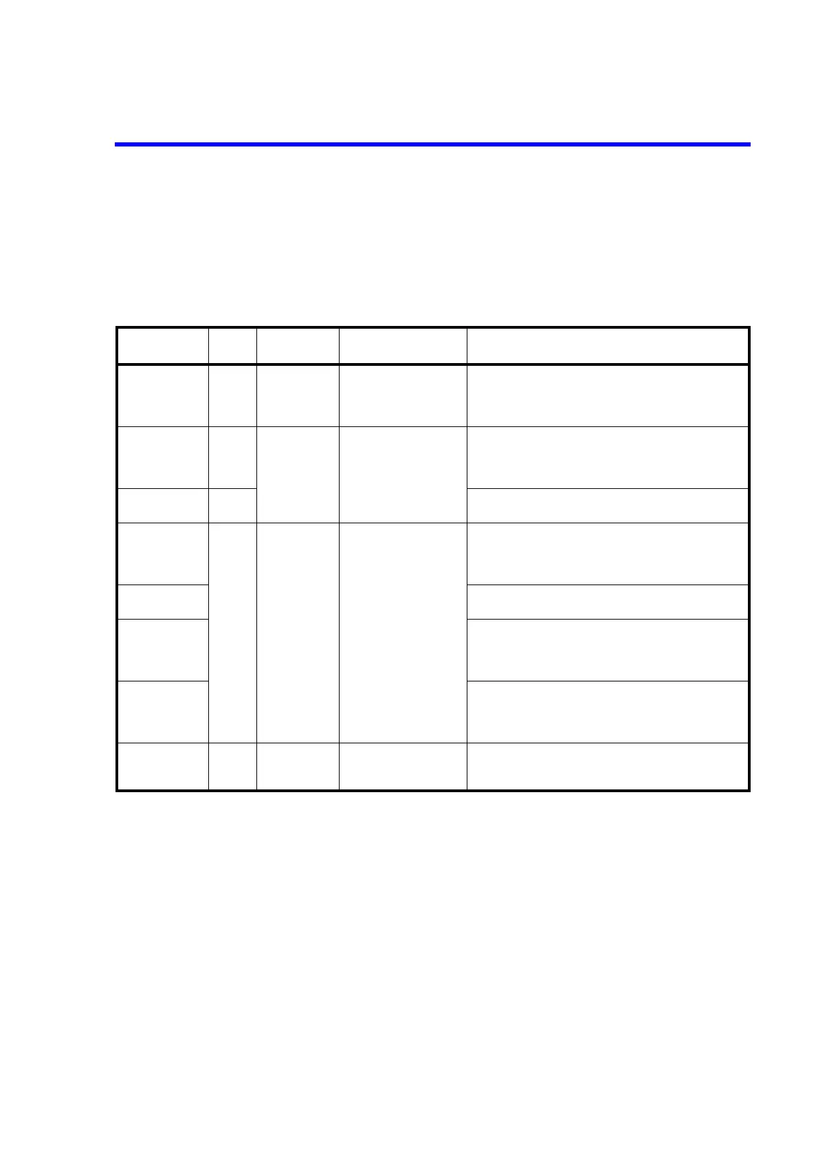
Table 5-12 shows the signal names, levels and functions.
Table 5-12 External Control Signal Functions
Signal
Input/
output
Level Impedance Function
TRIGGER IN Input TTL negative
pulse
(2 μs or more)
Approx. 4.7 kΩ • Measurement start in the DC source mode
• Pulse output in the Pulse source mode
• Start in the Sweep source mode
• Step-up
COMPLETE OUT
*1
Output TTL negative
pulse
(10 μs or more)
*3
Approx. 100 Ω open drain
(+5 V 10 kΩ pulled up)
• Measurement start signal (FRONT)
• Measurement complete and Period complete signal
(END)
• Comparator calculation result signal (HI/GO/LO)
SYNC OUT *1 Output • Pulse output signal in the Pulse source mode
• Step-up-signal in the Sweep source mode
INTERLOCK IN
*2
Input TTL negative
level
Approx. 10 kΩ • When this input signal is changed from “LO → HI”, the
output becomes Standby.
• When the signal is “HI” or Open, the output cannot be
changed to Operate.
STBY IN *2 • When this input signal is changed from “LO → HI”, the
output becomes Standby.
OPR/STBY IN
*2
• When this input signal is changed from “LO → HI”, the
output becomes Standby.
• When this input signal is changed from “HI → LO”, the
output becomes Operate.
OPR/SUS IN *2 • When this input signal is changed from “LO → HI”, the
output becomes Suspend.
• When this input signal is changed from “HI → LO”, the
output becomes Operate.
OPERATE OUT
*2
Output TTL negative
level
*3
Approx. 100 Ω open drain
(+5 V 10 kΩ pulled up)
• Outputs “LO” when Operate
• Outputs “HI” when Standby or Suspend
For *1 and *2, the same terminal is used by switching.
*1: SYNC OUT signal is not generated in the DC source mode.
*3: The output signal pulse width can be set to 100 μs.
 Loading...