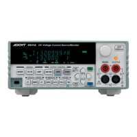
6241A/6242 DC Voltage Current Source/Monitor Operation Manual
A-1
APPENDIX
A.1 When Problems Occur (Before Requesting Repairs)
If problems are encountered when using the 6241A/6242, inspect the unit referring to Table A-1. If the prob-
lem cannot be solved by the suggested remedial actions, contact an ADC CORPORATION sales representa-
tive.
Fees will be charged for repairs by ADC CORPORATION even if the problem is one of those listed in Table
A-1. Therefore, carefully inspect the 6241A/6242 before requesting service.
Table A-1 Items to be Inspected before Requesting the Repair (1/2)
Q (Symptom) A (Cause and Solution)
1. Turning on the
POWER switch does
not display the screen.
Cause:
Solution:
Power fuse is open.
Replace it with the correct fuse.
2. Does not output the
set source value.
Cause:
Solution:
It is in Standby or Suspended status.
Set Operate and verify that the OPR indicator is ON.
Cause:
Solution:
Remote sensing setting is incorrect.
Verify the 4W/2W indicator on the front panel to see if the remote sens-
ing is set as desired.
Cause:
Solution:
Set at 0 V or 0 A.
Verify the source value.
Cause:
Solution:
Detection of an overload voltage (Over Load) has set it to Standby.
Remove the cable.
Cause:
Solution:
Heat detection (Over Heat) or Fan detection (Fan Stopped) has acti-
vated, setting it to Standby status.
Remove the cable and turn OFF the POWER switch.
Turn ON the POWER switch again.
Cause:
Solution:
The limiter is operating.
Verify the limiter setting.
Cause:
• OUTPUT terminal and SENSE terminal are incorrectly connected.
• SENSE is not connected correctly at 4-wire connection.
Solution: Verify cable connections again.
Cause: Entered Standby status due to the Interlock signal.
Solution:
• Change the Interlock setting to another setting.
• Set the Interlock signal LO.

 Loading...