6241A/6242 DC Voltage Current Source/Monitor Operation Manual
5.2.10 External Control Signals
5-57
5.2.10.2 Control of Scanner
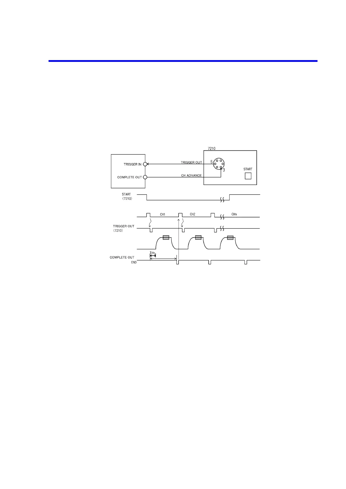
The following example shows how to control the 7210 scanner.
The following figure shows the timing and a connection diagram for an example in which measurement is
done in the Pulse source mode and the 7210 Channel switch is performed by the COMPLETE OUT (END)
signal.
Figure 5-15 Control of Scanner
(*1)
(*1) Select the output pulse to 100 μs.
Source and
Measurement
(6241A/6242)
(6241A/6242)
Tp
(6241A/6242)
Switch CH
(7210)