6241A/6242 DC Voltage Current Source/Monitor Operation Manual
6.3.2 Precautions when Using GPIB
6-6
6.3.2 Precautions when Using GPIB
1. Do not use connection cables to the measuring instrument and bus cables to controllers that are longer
than necessary. Ensure that the cables do not exceed 20 m in length. ADC offers the following stan-
dard bus cables.
2. The bus-cable connectors are piggyback type connects with both male and female sides. They can be
stacked on top of each other.
When connecting a bus-cable, do not connect three or more connectors on top of each other. Fully
tighten the connector screws.
3. Verify the power supply conditions, grounding status, and (if necessary) parameter settings for each
instrument before turning on each instrument.
Ensure that all instruments connected to the bus are turned on. The overall system operation cannot
be guaranteed if any of the instruments is not turned on.
4. Connecting and disconnecting cables
Turn off all connected instruments before connecting or disconnecting a GPIB cable with the chassis
commonly grounded for all the devices connected and to be connected. Use a common ground for the
chassis of each connected instrument.
5. ATN interrupt during message transmission
If an ATN request interruption occurs during transfer of messages between devices, the ATN has pri-
ority and the previous status is cleared.
6. When using the system in the talk-only mode, do not connect the controller.
7. Up to 255 characters can be recognized in a single program command transmission.
An error occurs if the program command exceeds 255 characters.
8. Retain the REN line at Low for 5 ms or longer following the transmission of program command.
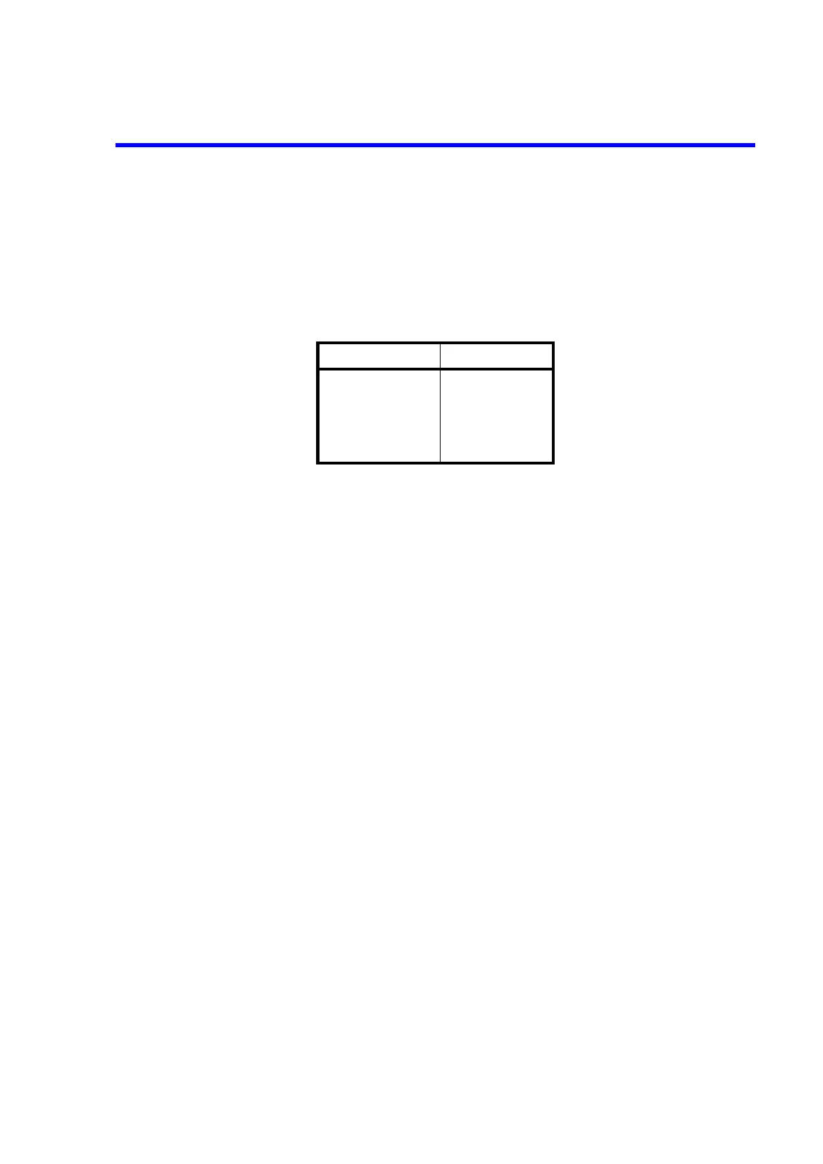
Table 6-2 Standard Bus Cable
Length Name
0.5 m 408JE-1P5
1 m 408JE-101
2 m 408JE-102
4 m 408JE-104