6241A/6242 DC Voltage Current Source/Monitor Operation Manual
5.1.5 Connecting with the Fixture 12701A
5-7
5.1.5 Connecting with the Fixture 12701A
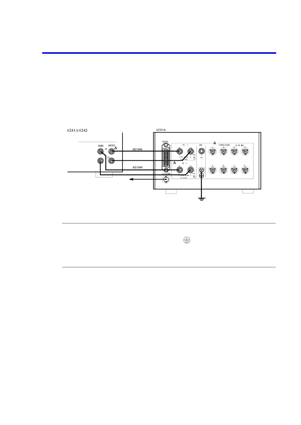
Figure 5-7 shows the connection with the 12701A.
The 4-wire connection is used.
The 2-wire connection does not require the SENSE connection.
For more information on the device connection inside the 12701A, refer to 12701A Instruction Manual.
Figure 5-7 Connection with the 12701A
CAUTION: Follow the procedure below to prevent electric shock.
1. Be sure to ground the 12701A protective ground terminal .
2. Connect 12701A LID SIGNAL to the INTERLOCK terminal at the 6241A/6242 rear panel, and set the param-
eter “OPR Signal” to InterLock In.
This enables the Interlock function, and the 6241A/6242 is set to Standby status when the 12701A cover is
released.
To INTERLOCK input terminal
on the rear panel
 Loading...