6241A/6242 DC Voltage Current Source/Monitor Operation Manual
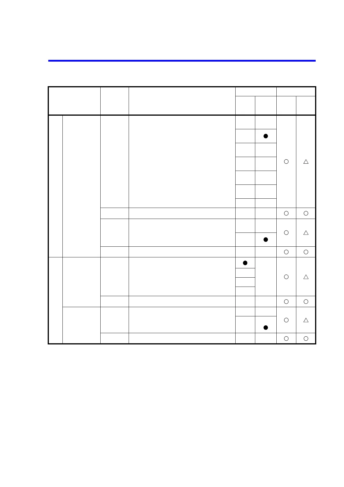
6.7.3 Remote Command List
6-36
System
Input and output
setting of the syn-
chronous control
signal
CP0 Outputs the COMPLETE signal. Meas Front (Measure-
ment Start)
CP1 Outputs the COMPLETE signal. Meas End (Measure-
ment End)
CP2 Outputs the COMPLETE signal. Comp HI
(Comparator calculation result is HI)
CP3 Outputs the COMPLETE signal. Comp GO (Compara-
tor calculation result is GO)
CP4 Outputs the COMPLETE signal. Comp LO (Compara-
tor calculation result is LO)
CP5 Outputs the COMPLETE signal. Comp HI or LO
(Comparator calculation result is HI or LO)
CP6 Outputs the Sync Out signal
CP? Response: CP0 to CP6
CW0 Specifies the synchronous control
signal output width: 10 µs
CW1 Specifies the synchronous control
signal output width: 100 µs
CW? Response: CW0 or CW1
GPIB Block delimiter DL0 CRLF<EOI>
*5
*8
DL1 LF
DL2 <EOI>
DL3 LF<EOI>
DL?
Response: DL0 to
DL3
Header output OH0 OFF
OH1 ON
*6
OH? Response: OH0 or OH1
*5: It is not initialized by RINI command.
*6: It is not initialized by RINI or *RST command.
*8: EOI is a GPIB function. It is not output by USB.
Item Command Description
Default Operation
Power
ON
Default
setting
During DC/
pulse
operation and
suspension
During
sweep
operation and
suspension
 Loading...