No. Title Page
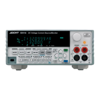
6253 DC Voltage Current Source/Monitor Operation Manual
LIST OF ILLUSTRATIONS
F-1
1-1 Output Range .................................................................................................................... 1-2
1-2 Operating Environment ..................................................................................................... 1-6
1-3 Setting Power Voltage Indicator ....................................................................................... 1-7
1-4 Changing Power Voltage, and Checking or Replacing Power Fuse ................................. 1-8
1-5 Power cable ....................................................................................................................... 1-9
1-6 Connecting Power Cable .................................................................................................. 1-10
1-7 Self-Test in Progress ......................................................................................................... 1-11
1-8 Self Test Completion ........................................................................................................ 1-11
1-9 Start-Up Screen ................................................................................................................. 1-12
1-10 VSIM Measurement Display (Output ON) ....................................................................... 1-12
2-1 Front Panel ........................................................................................................................ 2-1
2-2 Rear Panel ......................................................................................................................... 2-3
2-3 Home screen ..................................................................................................................... 2-5
2-4 Soft Keys at DC or Pulse Source (Top Layer) .................................................................. 2-7
2-5 Soft Keys at Sweep Source (Top Layer) .......................................................................... 2-7
2-6 MENU Hierarchy Operation ............................................................................................. 2-23
3-1 Linear Sweep .................................................................................................................... 3-5
3-2 Fixed Sweep ...................................................................................................................... 3-5
3-3 Multi-Slope Linear Sweep ................................................................................................ 3-7
4-1 Internal Connection ........................................................................................................... 4-1
4-2 2-Wire and 4-Wire Connections ....................................................................................... 4-3
4-3 Reducing Stray Capacitance and Lead Inductance ........................................................... 4-5
4-4 Preventing DUT Oscillation ............................................................................................. 4-6
4-5 Preventing 6253 Oscillation .............................................................................................. 4-6
4-6 Connection for High Current Measurement ..................................................................... 4-7
4-7 Connection with 12701A .................................................................................................. 4-8
4-8 Random Sweep and Random Pulse Sweep ....................................................................... 4-21
4-9 Multi-Slope Linear Sweep ................................................................................................ 4-22
4-10 Multi-Slope Linear Pulse Sweep ...................................................................................... 4-23
4-11 Output Status Transitions .................................................................................................. 4-30
4-12 Rechargeable Battery Charge and Discharge Operations ................................................. 4-42
4-13 Basic Source and Measurement Timing ........................................................................... 4-45
4-14 Settling Time and Measurement Delay Time ................................................................... 4-51
4-15 NULL Calculation Timing ................................................................................................ 4-57
4-16 Connections for 3-Unit Synchronous Operation by SYNC OUT ..................................... 4-66
4-17 Serial Connection .............................................................................................................. 4-69
4-18 Parallel Connection ........................................................................................................... 4-70
4-19 Conceptual Diagram of Memory Store ............................................................................. 4-71
5-1 Status Register Structure ................................................................................................... 5-15
5-2 Status Byte Register Structure .......................................................................................... 5-16
7-1 Connections for Calibration .............................................................................................. 7-3


 To Next Page