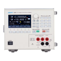
6253 DC Voltage Current Source/Monitor Operation Manual
7.5.1 Overall Calibration Procedure
7-13
7.5.1 Overall Calibration Procedure
This section describes the overall calibration procedure according to Figure 7-2 Calibration Procedure (1).
1. Enter the calibration mode by CAL1.
2. When executing all the calibrations, initialize calibration data only once by XINI
at the start of the calibrations.
3. When executing voltage calibration, make connection in reference to Figure 7-1
Connections for Calibration (a). When executing current calibration, make
connection in reference to Figure 7-1 Connections for Calibration (b) and Figure
7-1 Connections for Calibration (c).
4. Set the output status to Operate in the calibration mode by OPR.
5. Execute voltage calibration according to Figure 7-3 Calibration Procedure (2)
and Figure 7-4 Calibration Procedure (3), or execute current calibration
according to Figure 7-5 Calibration Procedure (4), Figure 7-6 Calibration
Procedure (5), Figure 7-7 Calibration Procedure (6) and Figure 7-8 Calibration
Procedure (7).
6. Set the output status to Standby by SBY.
7. Store the calibration data to the non-volatile memory by XWR.
8. Finish the calibration mode by CAL0.
7.5.2 Voltage Source/Voltage Limit Calibration
1. Select the voltage calibration mode.
Voltage source: XVS
Voltage HI limit: XVLH
Voltage LO limit: XVLL
2. Select the range.
300 mV range: XR3
3 V range: XR4
10 V range: XR0
30 V range: XR5
100 V range: XR6
3. Enter the DMM data input mode by XDAT.
4. Set the DMM read value by XD data.
5. Move to the full-scale calibration mode by XNXT.
6. Set the DMM read value by XD data.
7. Finish the DMM data input mode by XNXT.
8. Move to the zero calibration data fine adjustment mode by XADJ.