2D-LC User Guide 109
5 2D-LC Data Acquisition in MassHunter Workstation 11
2D-LC User Interface
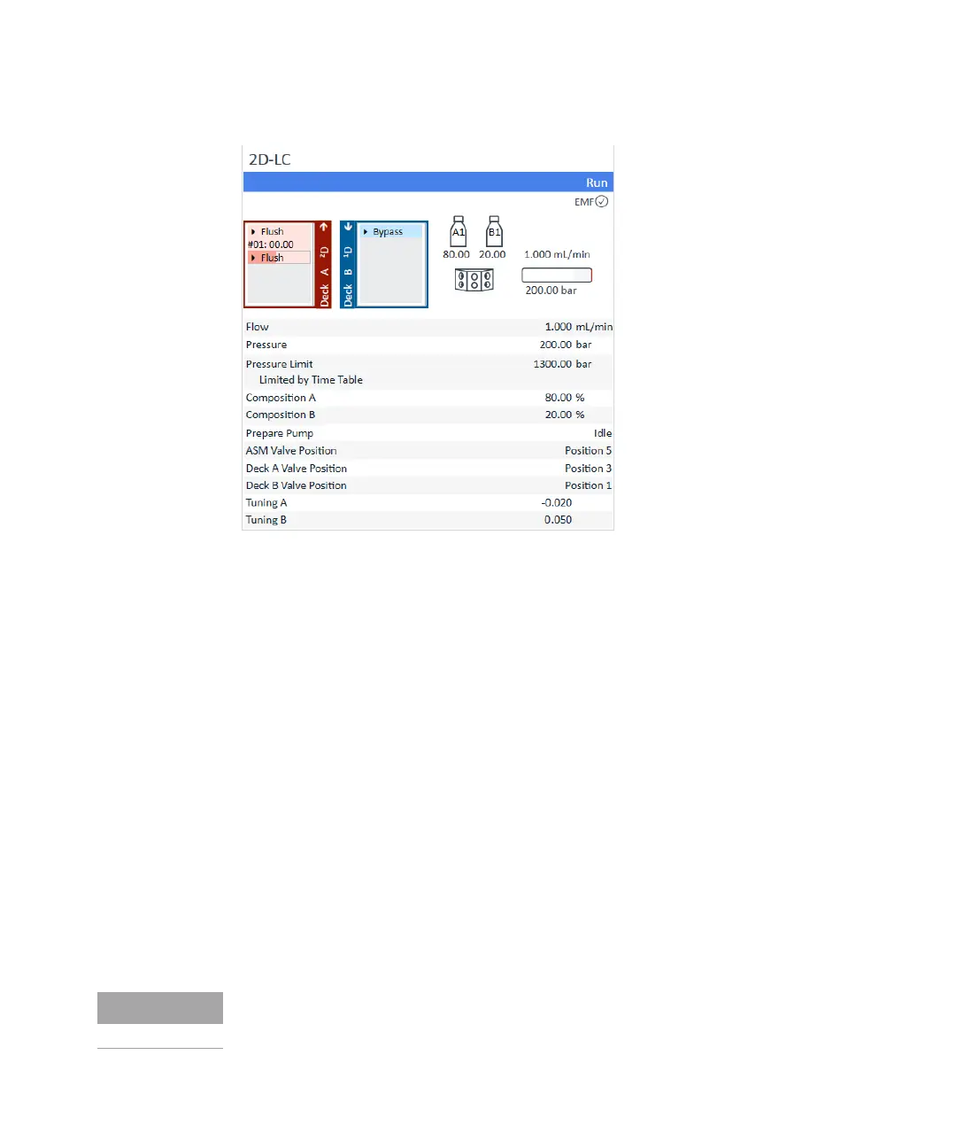
Figure 55 Full view of the 2D-LC UI
Flow The current solvent flow rate (in mL/min).
Pressure The current pump pressure (in bar, psi or MPa)
Pressure Limit The current maximum pressure limit.
Composition A:B The current solvent composition. When a solvent selection valve is fitted,
the channels are shown in the graphic.
Prepare Pump The info represents the current pump status.
2D-LC Valve position The info represents the current 2D-LC Valve status. In the current setup an
ASM Valve(Position 1-5) is installed see “Connecting the 2D-LC Valve, ASM
(G4243A)” on page 70
Deck A Valve position The info represents the current MHC Valve status Deck A (Position 1-6)
Deck B Valve position The info represents the current MHC Valve status Deck B (Position 1-6)
Diverter Valve Position The info represents the current valve position (Position 1 → Into MSD,
Position 2 → Into waste).
Tuning The signal represents the current effort the pump drives have to take to
maintain the current system status.
For further information, see the pump user manual.

 Loading...


