132 Chapter2
Making Measurements
Example 11: Time-Gated Measurement
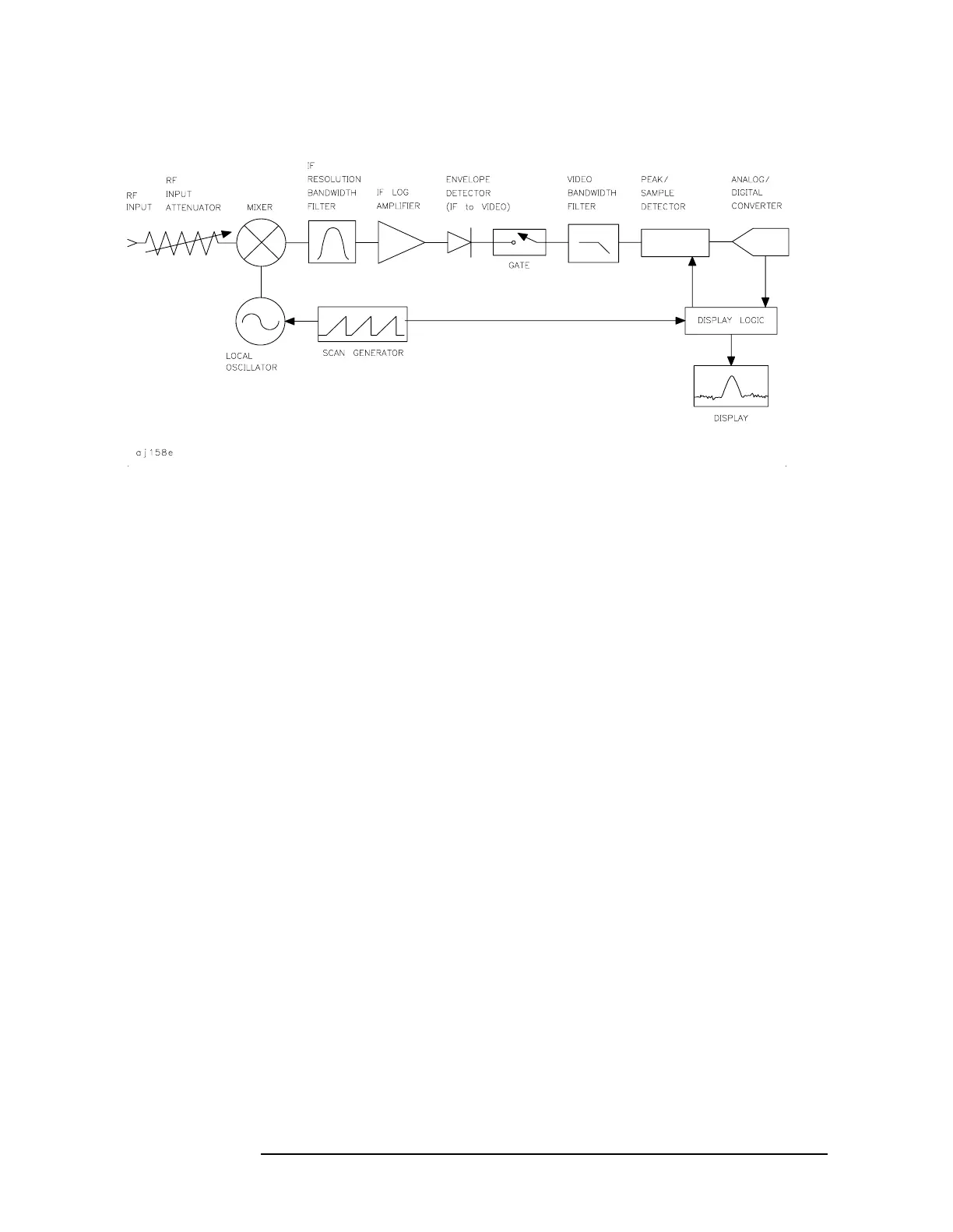
Figure 2-62 Block Diagram of the Spectrum Analyzer with Time Gate
The gate within the analyzer is opened and closed based on four factors:
• An externally supplied transistor-transistor logic (TTL) signal.
• The gate control, or trigger mode (positive or negative edge
triggering, or positive or negative level triggering).
• The gate delay setting, which determines how long after the trigger
signal the gate actually becomes active for the edge trigger mode.
• The gate length setting, which determines how long the gate is on for
the edge trigger mode.
To understand time-gating better, consider a spectrum measurement
performed on two pulsed-RF signals. You need to consider the timing
interaction of three key signals that are present during this
measurement. The three signals are:
• The pulsed-RF signal under test.
• The gate trigger signal, supplied from the signal source.
• The gate output signal, available from a BNC connector on the rear
panel of the spectrum analyzer. This transistor-transistor logic
(TTL) signal is low when the gate is "off" (masking) and high when
the gate is "on" (measuring).
The timing interactions between the three key signals are best
understood if you observe them first on a oscilloscope. Figure 2-63
shows each of the signals as the would appear on the oscilloscope.
Keep in mind the main goal: to measure the spectrum of pulse train
number 1 and determine if it has any low-level modulation or spurious
signals.
 Loading...
