Chapter 2 85
Making Measurements
Example 7: Stimulus-Response Measurements
The same measurement can be made using an 8560E/EC (without
Option 002), Agilent 8561E/EC, Agilent 8562E/EC, Agilent 8563E/EC,
Agilent 8564E/EC or Agilent 8565E/EC spectrum analyzer with an
Agilent 85640A, Agilent 85644A, or Agilent 85645A tracking generator.
This example illustrates several functions in the 8560E/EC Option 002
tracking-generator menu: adjusting the tracking-generator output
power, source calibration, and normalization.
Because the procedure for conducting a reflection measurement is
similar, use this example as your guide. You may also refer to the
Agilent Technologies Spectrum Analyzer Seminar, Application Note
150-7, or Applicaton Note 1212 for more information about reflection
measurements.
Stepping through the Measurement
There are four basic steps for performing any stimulus-response
measurement (either transmission or reflection):
1. Set up the spectrum analyzer settings
2. Calibrate
3. Normalize
4. Measure
Set up the test
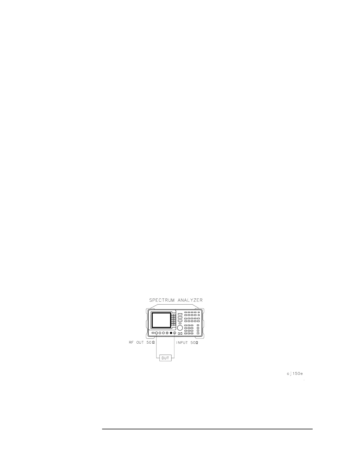
1. To measure the rejection of a bandpass filter, connect the equipment
as shown in Figure 2-30. This example uses a bandpass filter with a
center frequency of 321.4 MHz and a specified rejection of −85 dB, as
the device under test (DUT).
Figure 2-30 Transmission Measurement Test Setup
 Loading...
