62 Chapter2
Making Measurements
Example 3: Modulation
The following equation also determines percentage of modulation using
amplitude units in volts:
Frequency Modulation
This section contains general information about frequency modulation,
as well as a procedure for calculating FM deviation using a spectrum
analyzer.
For sinusoidal modulation where either the modulation frequency or
the FM deviation can be varied, the spectrum analyzer can be used to
accurately set up a modulation index corresponding to a Bessel null.
The following example illustrates how to verify the FM deviation
accuracy of a signal generator with FM capability. We will use a carrier
frequency of 100 MHz and test for FM deviation accuracy at a 25 kHz
rate using the modulation index for the first carrier null (2.401). Figure
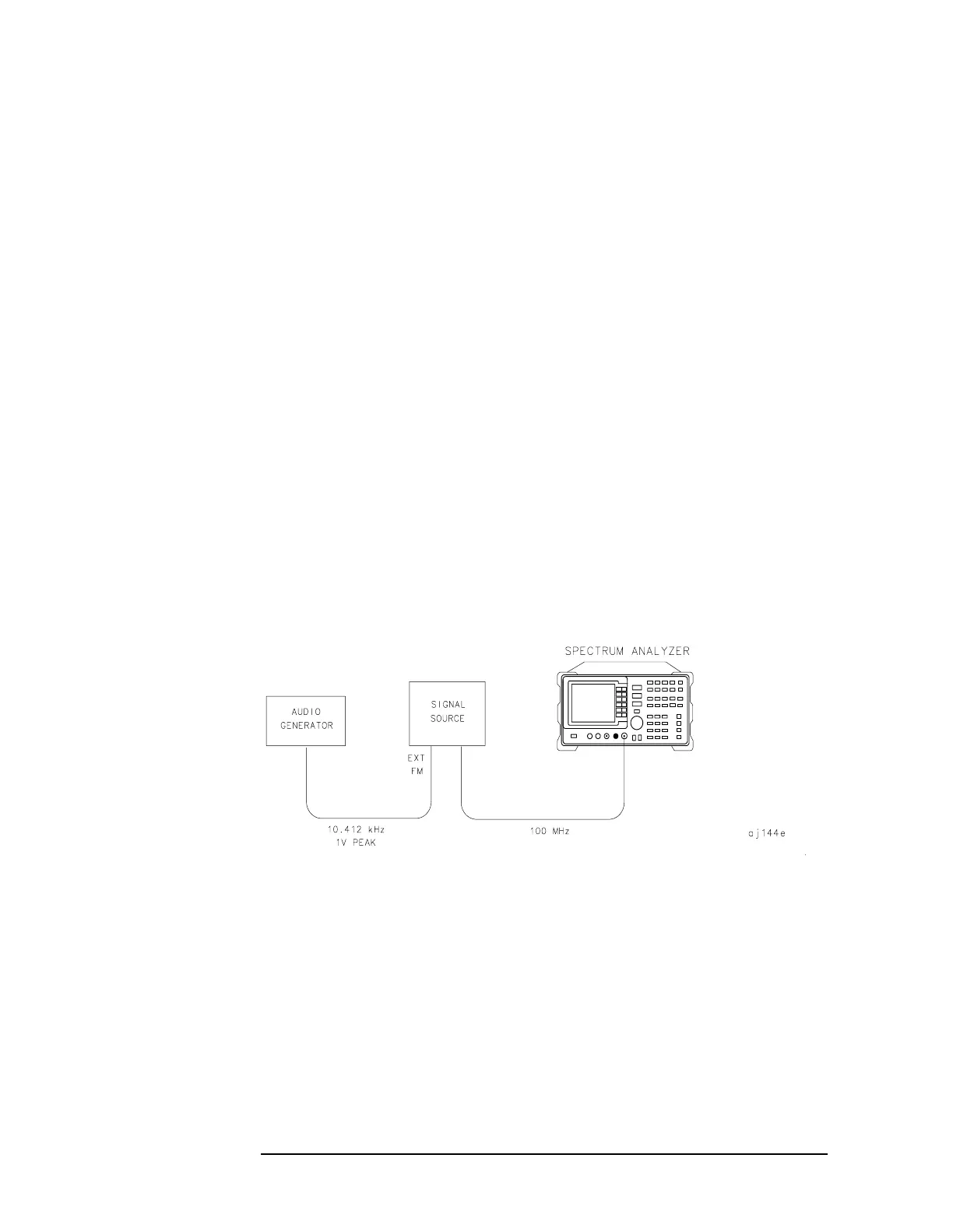
2-9 illustrates how to set up the equipment for this measurement.
Figure 2-9 FM Deviation Test Setup
1. Connect the signal source to the spectrum analyzer INPUT 50Ω. Set
the source to 100 MHz.
2. Press
PRESET to begin with the spectrum analyzer in a preset state
and change the settings as follows:
a. Set center frequency to 100 MHz.
b. Set span to 100 kHz.
c. Set resolution bandwidth to 1 kHz.
d. Set video bandwidth to 1 kHz.
where A
s
= sideband amplitude, in volts
A
c
= carrier amplitude, in volts
M
2A
s
100×
A
c
------------------------=
 Loading...
