Agilent X-Series Signal Generators User’s Guide 101
Optimizing Performance
Using Flatness Correction
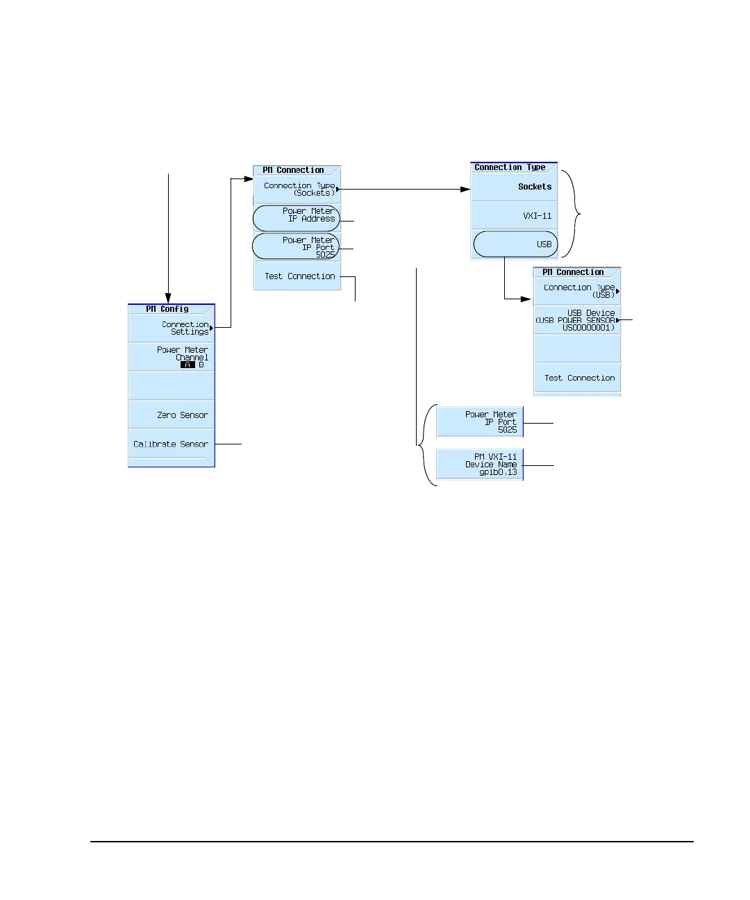
Figure 5-17 Configure Power Meter Menu Softkeys
Basic Procedure
1. Create a user flatness array.
a. Configure the power meter/sensor
b. Connect the equipment
c. Configure the signal generator
d. Enter the user flatness correction values
2. Optionally, save the user flatness correction data.
3. Apply user flatness correction to the RF Output.
AMPTD > More > User
Flatness > Configure Power
Meter
Sockets LAN: Sets the
IP port to 5025 (standard)
or 5023 (telnet)
programming.
Sets the power meter’s IP
address or LAN–GPIB
gateway’s IP address
(Sockets LAN and VXI–11
LAN only).
VXI–11 LAN: Opens a
menu for entering a
device name for the
power meter being used.
Enables the power meter
connection type: Sockets
LAN, VXI–11 LAN, or USB.
Note: The VXI–11 softkey is
used to communicate
remotely with a power meter
that has a GPIB connector
via LAN–GPIB gateway.
USB U2000A Series Power
Meters do not require the
sensor to be calibrated.
For details on each key, use key help as
described on page 44.
Open a menu
to enter the
USB device
name.
This softkey is dependent
on the selected
Connection Type.
Attempts to connect to the
specified external power
meter and execute a
“*IDN?” command. If the
result is “Connected, but no
*IDN? response”, then the
IP address connected to
something, but the socket
port or VXI-11 device name
was not correct.

 Loading...

