280 Agilent X-Series Signal Generators User’s Guide
Digital Signal Interface Module (Option 003/004)
Operating the N5102A Module in Input Mode
Operating the N5102A Module in Input Mode
This section shows how to set the parameters for the N5102A module using the signal generator UI
in the input direction. Each procedure contains a figure that shows the softkey menu structure for
the interface module function being performed.
Refer to “Connecting the Clock Source and the Device Under Test” on page 265 and configure the test
setup.
Accessing the N5102A Module User Interface
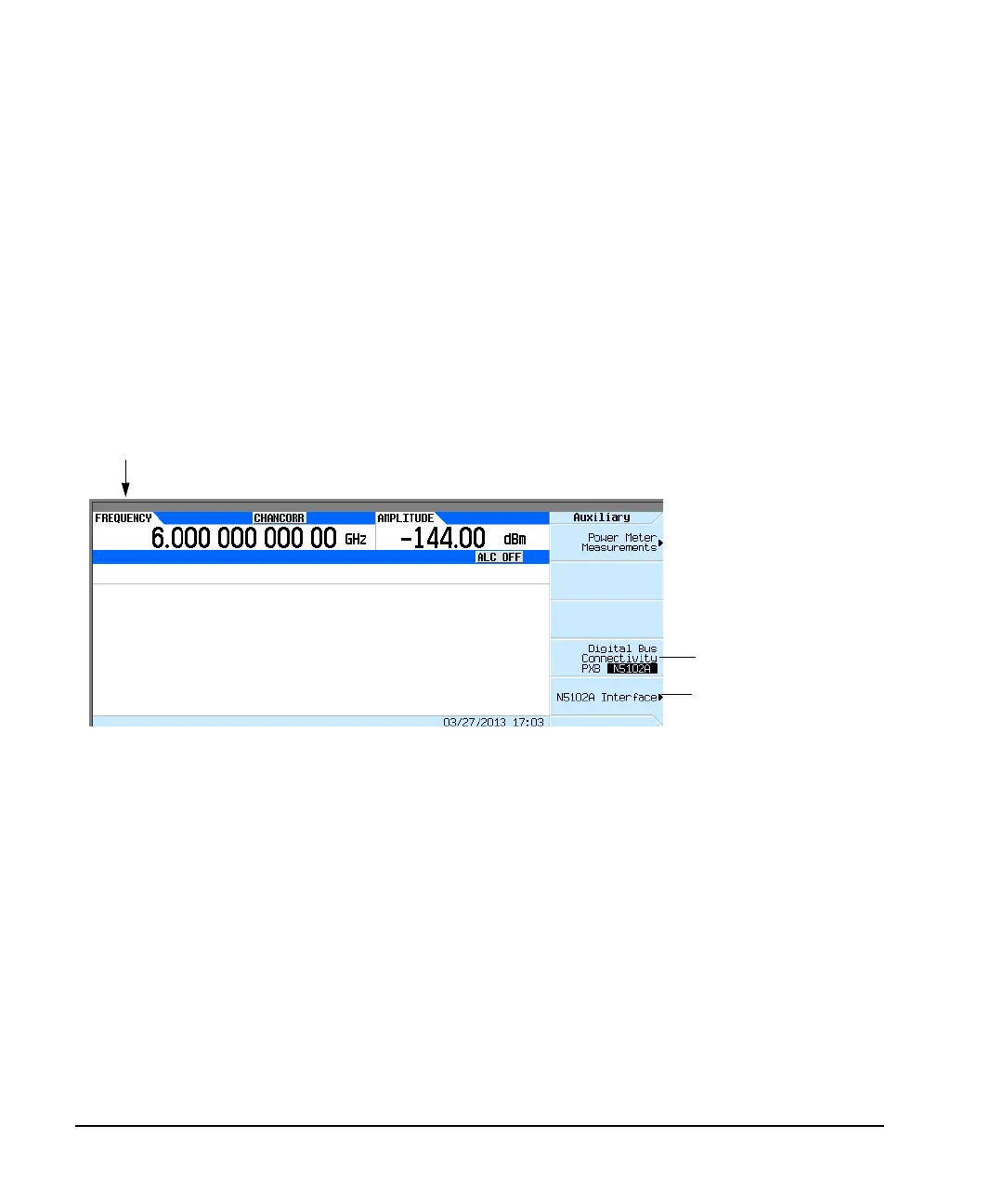
Figure 10- 16 shows the Auxiliary menu that is accessed by pressing the Aux Fctn key on the front
panel of the signal generator.
Figure 10-16 First-Level Softkey Menu
All parameters for the N5102A module are set with softkeys on the signal generator.
Press N5102A Interface to access the UI (first-level softkey menu shown in Figure 10- 17) that is used
to configure the digital signal interface module. Notice the graphic in the signal generator display,
showing a setup where the N5102A module is generating its own internal clock signal. This graphic
changes to reflect the current clock source selection.
Select either PXB or N5102A
connectivity.
The default selection is N5102A.
Aux Fctn
Press here to access the N5102A
menu.

 Loading...

