256 Agilent X-Series Signal Generators User’s Guide
Digital Signal Interface Module (Option 003/004)
Clock Timing
sample rate is reduced by the clocks per sample value when the value is greater than one. For an IF
signal or an input signal, clocks per sample is always set to one. Refer to
Table 10- 5 for the Output
mode parallel and parallel interleaved port configuration clock rates.
For Input mode, the maximum clock rate is limited by the following factors:
•sample size
• data type
Refer to Table 10- 6 for the Input mode parallel and parallel interleaved port configuration clock
rates.
Clock Source
The clock signal for the N5102A module is provided in one of three ways through the following
selections:
• Internal: generated internally in the interface module (requires an external reference)
• External: generated externally through the Ext Clock In connector
•Device: generated externally through the Device Interface connector
The clock source is selected using the N5102A module UI on the signal generator, see Figure 10- 2.
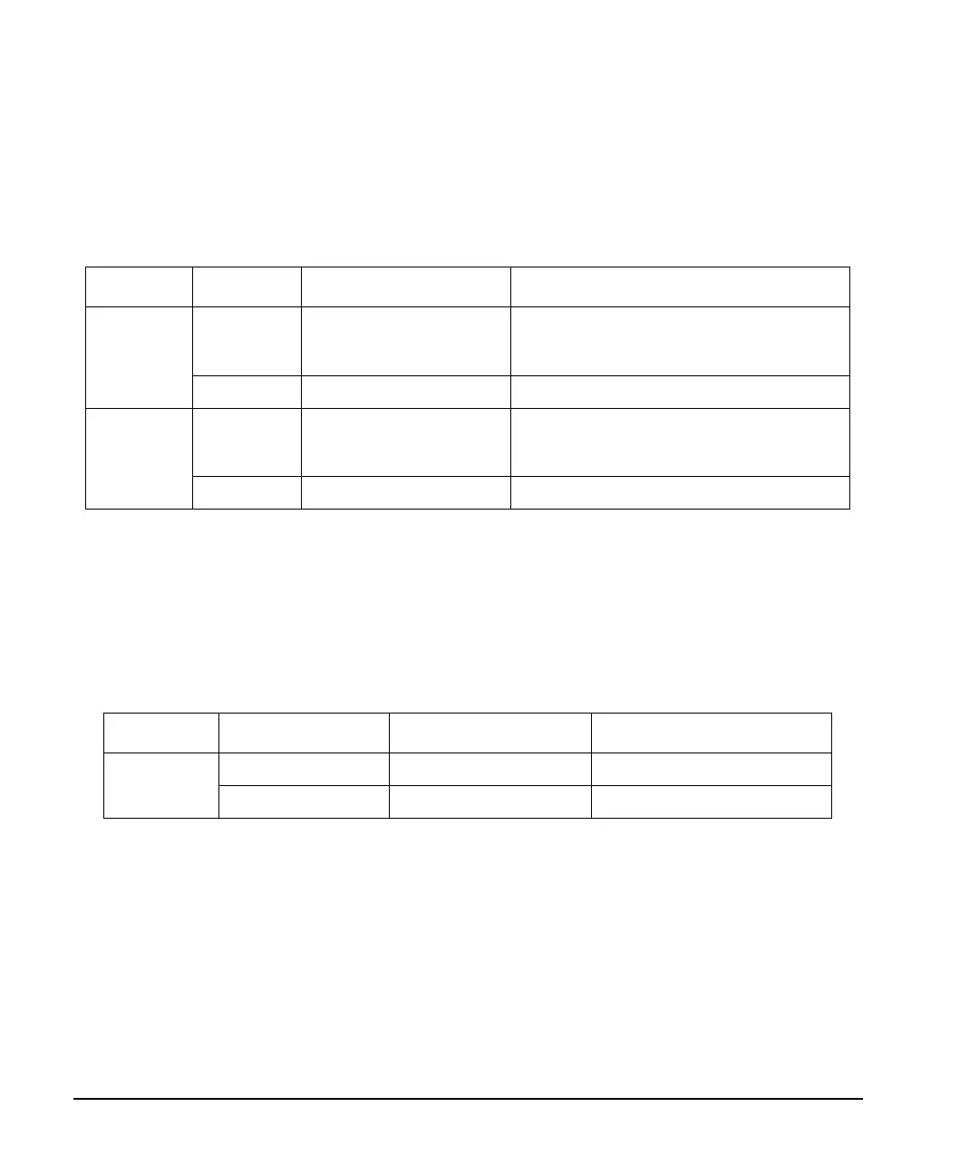
Ta bl e 10-5 Output Parallel and Parallel Interleaved Clock Rates
Logic Type Signal Type Minimum Rate Maximum Rate
LVDS IQ 1 x (clocks/sample) kHz the smaller of: 100 x (clocks /sample) MHz
or
400 MHz
IF 4 kHz 400 MHz
Other IQ 1 x (clocks/sample) kHz the smaller of: 100 x (clocks /sample) MHz
or
150 MHz
IF 4 kHz 150 MHz
Ta bl e 10-6 Input Parallel and Parallel Interleaved Clock Rates
Logic Type Data Type Minimum Rate Maximum Rate
N/A Samples 1 kHz 200 MHz
Pre- FIR Samples 1 kHz 100 MHz

 Loading...

