Agilent X-Series Signal Generators User’s Guide 265
Digital Signal Interface Module (Option 003/004)
Connecting the Clock Source and the Device Under Test
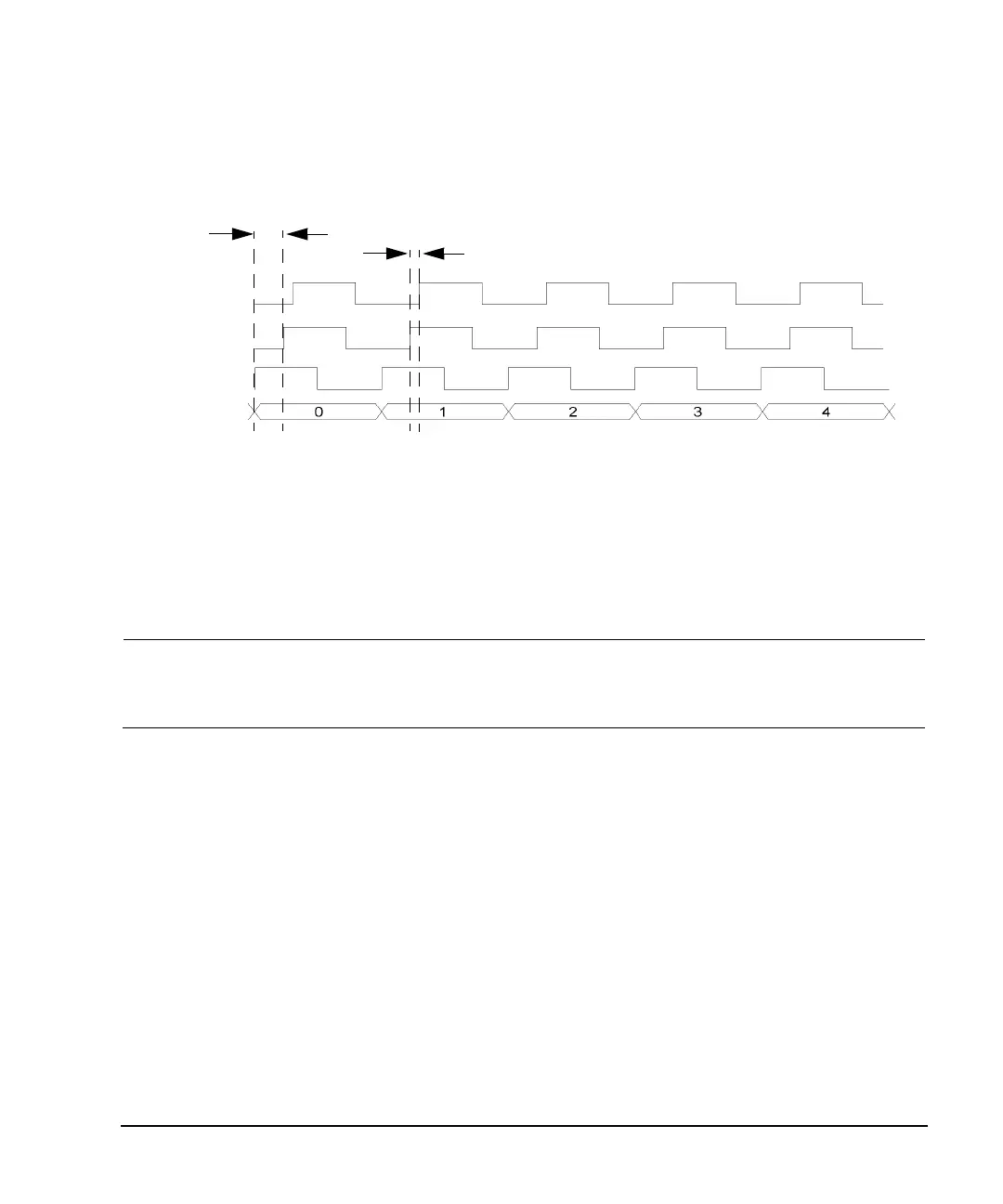
Figure 10-7 Clock Phase and Skew Adjustments
Connecting the Clock Source and the Device Under Test
As shown in Figure 10- 3 on page 258, there are numerous ways to provide a common frequency
reference to the system components (signal generator, N5102A module, and the device under test).
Figure 10- 8 shows an example setup where the signal generator supplies the common frequency
reference and the N5102A module is providing the clock to the device.
CAUTION The Device Interface connector on the interface module communicates using high speed
digital data. Use ESD precautions to eliminate potential damage when making
connections.
Clock skew adjustment
90 degree phase adjustment
Clock
Phase adjusted
skew adjusted
clock
clock
Data
Phase and

 Loading...

