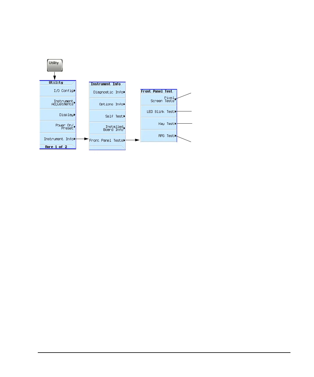
Home
Agilent Technologies
Portable Generator
X Series
Agilent Technologies X Series User Manual
4
of 1
of 1 rating
426 pages
Give review
Manual
Specs
To Next Page
To Next Page
To Previous Page
To Previous Page
Loading...
Agilent X-Series Signal Generators User’
s Guide
38
9
T
roubleshooting
Front Pane
l T
ests
Front Panel T
ests
Set all display pixels to the se
lected color.
T
o
return to normal oper
ation, press any key
.
Blink RF On/Off,
Mod on/Off, and More LEDs
Correct oper
ation:
Full CCW = –10
Full CW = 10
Displays a keyboard map.
As you press a key
, the map indicates the key location.
For details on each key
, use key help
as described
on
page 44
.
402
404
Table of Contents
Table of Contents
3
Signal Generator Overview
15
Signal Generator Features
16
Modes of Operation
18
Continuous Wave
18
Swept Signal
18
Analog Modulation
18
Digital Modulation (Vector Models with Option 65X Only)
18
Front Panel Overview
19
Host USB
19
Display
19
Softkeys
20
Numeric Keypad
20
Arrows and Select
20
Page up
20
Menus
20
Trigger
21
Local Cancel/(Esc)
21
Help
21
Preset and User Preset
21
RF Output (N5171B, N5172B, N5181B, N5182B)
21
RF Output (N5173B, N5183B)
21
RF On/Off and LED
21
Mod On/Off and LED
21
Page down
22
I Input (Vector Models Only)
22
Q Input (Vector Models Only)
22
Knob
22
Incr Set
22
Return
22
More and LED
22
Power Switch and Leds
23
Front Panel Display
24
Active Function Area
24
Frequency Area
24
Annunciators
24
Amplitude Area
25
Error Message Area
26
Text Area
26
Softkey Label Area
26
Rear Panel Overview (N5171B, N5172B, N5181B, & N5182B)
27
AC Power Receptacle
27
Ext 1 & Ext 2
28
Lf out
28
Sweep out
28
Pulse
28
Trig 1 & 2
28
Ref in
28
Mhz out
29
Gpib
29
Lan
29
Device USB
29
Host USB
29
SD Card
29
Digital Modulation Connectors (Vector Models Only)
30
I Out, Q Out, Out, out
30
Bb Trig 1 & Bb Trig 2
31
Event 1
31
Pat Trig
31
Digital Bus I/O
31
AUX I/O Connector
32
Rear Panel Overview (N5173B & N5183B)
37
AC Power Receptacle
37
Ext 1 & Ext 2
38
Lf out
38
Sweep out
38
Pulse
38
Trig 1 & 2
38
Ref in
38
Mhz out
39
Gpib
39
Lan
39
Device USB
39
Host USB
39
SD Card
39
Alc Input
39
Z Axis Output
40
Setting Preferences & Enabling Options
42
User Preferences
42
Display Settings
42
Power on and Preset
43
Front Panel Knob Resolution
44
Setting Time and Date
44
Reference Oscillator Tune
45
Upgrading Firmware
45
Remote Operation Preferences
46
GPIB Address and Remote Language
46
Configuring the LAN Interface
47
Enabling LAN Services: "Browser," "Sockets," and "VXI-11
48
Configuring the Remote Languages
49
Configuring the Preset Languages
51
Enabling an Option
53
Viewing Options and Licenses
54
Hardware Assembly Installation and Removal Softkeys
55
Basic Operation
58
Presetting the Signal Generator
58
Viewing Key Descriptions
58
Entering and Editing Numbers and Text
59
Entering Numbers and Moving the Cursor
59
Entering Alpha Characters
59
Example: Using a Table Editor
60
Setting Frequency and Power (Amplitude)
61
Example: Configuring a 700 Mhz, −20 Dbm Continuous Wave Output
62
Using an External Reference Oscillator
62
Setting ALC Bandwidth Control
63
Configuring a Swept Output
64
Routing Signals
66
Step Sweep
66
List Sweep
69
Example: Using a Single Sweep
72
Example: Manual Control of Sweep
73
Modulating the Carrier Signal
73
Example
73
Simultaneous Modulation
75
Working with Files
75
File Softkeys
76
Viewing a List of Stored Files
77
Storing a File
79
Loading (Recalling) a Stored File
80
Moving a File from One Media to Another
81
Working with Instrument State Files
82
Selecting the Default Storage Media
86
Reading Error Messages
87
Error Message Format
87
Using Analog Modulation (Option UNT)
90
Analog Modulation Waveforms
90
Analog Modulation Sources
90
Using an Internal Modulation Source
92
Using an External Modulation Source
93
Removing a DC Offset
93
Using Wideband am
93
Configuring the LF Output (Option 303)
95
LF out Modulation Sources
95
Configuring the LF Output with an Internal Modulation Source
96
Configuring the LF Output with a Function Generator Source
97
Optimizing Performance
99
Using the Dual Power Meter Display
100
Example: Dual Power Meter Calibration
103
Using the Power Meter Servo
108
Power Meter Servo Configuration
109
Example
110
Using Flatness Correction
111
Creating a User Flatness Correction Array
113
Recalling and Applying a User Flatness Correction Array
119
Using Internal Channel Correction (N5172B/82B Only)
120
Configure Internal Channel Correction
123
Perform Enhanced Factory Calibration
123
Using External Leveling (N5173B/83B Only)
124
Option 1E1 Output Attenuator Behavior and Use
127
Configure External Leveling
128
Using Unleveled Operating Modes
132
ALC off Mode
133
Power Search Mode
133
Using an Output Offset, Reference, or Multiplier
136
Setting an Output Offset
136
Setting an Output Reference
137
Setting a Frequency Multiplier
138
Using the Frequency and Phase Reference Softkeys
140
Using Free Run, Step Dwell, and Timer Trigger
140
Understanding Free Run, Step Dwell, and Timer Trigger Setup
140
Using a USB Keyboard
142
Using Pulse Modulation (Option UNW or 320)
144
Pulse Characteristics
145
The Basic Procedure
147
Example
147
Pulse Train (Option 320 - Requires: Option UNW)
149
Basic Digital Operation-No BBG Option Installed
155
I/Q Modulation
156
Configuring the Front Panel Inputs
157
Basic Digital Operation (Option 653/655/656/657)
159
Waveform File Basics
160
Signal Generator Memory
160
Dual ARB Player
160
Storing, Loading, and Playing a Waveform Segment
162
Loading a Waveform Segment into BBG Media
162
Storing/Renaming a Waveform Segment to Internal or USB Media
163
Playing a Waveform Segment
163
Waveform Sequences
165
Creating a Sequence
166
Viewing the Contents of a Sequence
167
Editing a Sequence
167
Playing a Sequence
168
Saving a Waveform's Settings & Parameters
169
Viewing and Modifying Header Information
171
Viewing & Editing a Header Without Selecting the Waveform
173
Using Waveform Markers
175
Waveform Marker Concepts
176
Accessing Marker Utilities
180
Viewing Waveform Segment Markers
181
Clearing Marker Points from a Waveform Segment
181
Setting Marker Points in a Waveform Segment
182
Viewing a Marker Pulse
185
Using the RF Blanking Marker Function
186
Setting Marker Polarity
188
Controlling Markers in a Waveform Sequence
188
Using the EVENT Output Signal as an Instrument Trigger
191
Triggering a Waveform
192
Trigger Type
193
Trigger Source
194
Example: Segment Advance Triggering
195
Example: Gated Triggering
196
Example: External Triggering
198
Clipping a Waveform
199
How Power Peaks Develop
200
How Peaks Cause Spectral Regrowth
202
How Clipping Reduces Peak-To-Average Power
203
Configuring Circular Clipping
206
Configuring Rectangular Clipping
207
Scaling a Waveform
208
How DAC Over-Range Errors Occur
209
How Scaling Eliminates DAC Over-Range Errors
210
Setting Waveform Runtime Scaling
211
Setting Waveform Scaling
212
Setting the Baseband Frequency Offset
214
DAC Over-Range Conditions and Scaling
216
I/Q Modulation
218
Using the Rear Panel I and Q Outputs
220
Configuring the Front Panel Inputs
221
I/Q Adjustments
222
I/Q Calibration
224
Using the Equalization Filter
226
Using Finite Impulse Response (FIR) Filters in the Dual ARB Real-Time Modulation Filter
228
Creating a User-Defined FIR Filter Using the FIR Table Editor
229
Modifying a FIR Filter Using the FIR Table Editor
234
Loading the Default Gaussian FIR File
235
Modifying the Coefficients
236
Storing the Filter to Memory
237
Setting the Real-Time Modulation Filter
238
Multiple Baseband Generator Synchronization
239
Understanding the Master/Slave System
242
Equipment Setup
243
Configuring the Setup
243
Making Changes to the Multiple Synchronization Setup and Resynchronizing the Master/Slave System
245
Understanding Option 012 (lo In/Out for Phase Coherency) with Multiple Baseband Generator Synchronization
246
Configuring the Option 012 (lo In/Out for Phase Coherency) with MIMO
246
Real-Time Applications
250
Waveform Licensing
251
Understanding Waveform Licensing
251
Installing an Option N5182-22X or Option N5182B-25X
251
Licensing a Signal Generator Waveform
251
Adding Real-Time Noise to a Signal (Option 403)
259
Adding Real-Time Noise to a Dual ARB Waveform
259
Eb/No Adjustment Softkeys for Real Time I/Q Baseband AWGN
262
Using Real Time I/Q Baseband AWGN
265
Digital Signal Interface Module (Option 003/004)
267
Clock Timing
267
Clock and Sample Rates
267
Clock Source
270
Common Frequency Reference
271
Clock Timing for Parallel Data
273
Clock Timing for Parallel Interleaved Data
276
Clock Timing for Serial Data
278
Clock Timing for Phase and Skew Adjustments
278
Connecting the Clock Source and the Device under Test
279
Data Types
282
Output Mode
282
Input Mode
282
Operating the N5102A Module in Output Mode
283
Setting up the Signal Generator Baseband Data
283
Accessing the N5102A Module User Interface
283
Choosing the Logic Type and Port Configuration
285
Selecting the Output Direction
286
Selecting the Data Parameters
286
Configuring the Clock Signal
288
Generating Digital Data
293
Operating the N5102A Module in Input Mode
294
Accessing the N5102A Module User Interface
294
Selecting the Input Direction
296
Choosing the Logic Type and Port Configuration
296
Configuring the Clock Signal
297
Selecting the Data Parameters
301
Digital Data
304
BERT (Option UN7)
305
Bit Error Rate Tester-Option UN7
306
Block Diagram
306
Clock Gate Function
306
Clock/Gate Delay Function
307
Clock Delay Function
309
Gate Delay Function in the Clock Mode
310
Triggering
311
Data Processing
314
Repeat Measurements
315
Testing Signal Definitions
316
Verifying BERT Operation
318
Measurement Setup Using Self-Test Mode
318
Measurement Example Using Custom Digital Modulation (Requires Option 431)
321
Real-Time Phase Noise Impairments (Option 432)
323
Real-Time Phase Noise Impairment
324
The Agilent X-Series Phase Noise Shape and Additive Phase Noise Impairments
325
Understanding the Phase Noise Adjustments
327
DAC Over-Range Conditions and Scaling
328
Custom Digital Modulation (Option 431)
329
Custom Modulation
330
ARB Custom Modulation Waveform Generator
330
Real-Time Custom Modulation Waveform Generator
330
Creating and Using Bit Files
338
Creating a User File
339
Renaming and Saving a User File
341
Recalling a User File
342
Modifying an Existing User File
342
Applying Bit Errors to a User File
343
Using Customized Burst Shape Curves
344
Understanding Burst Shape
344
Creating a User-Defined Burst Shape Curve
347
Storing a User-Defined Burst Shape Curve
349
Recalling a User-Defined Burst Shape Curve
349
Using the Arbitrary Waveform Generator
351
Using Predefined Custom Digital Modulation
351
Creating a Custom Digital Modulation State
353
Storing a Custom Digital Modulation State
355
Recalling a Custom Digital Modulation State
357
Defining a Modulation
358
Creating a Custom Multicarrier Digital Modulation State
364
Storing a Custom Multicarrier Digital Modulation State
366
Applying Changes to an Active Multicarrier Digital Modulation State
366
Using Finite Impulse Response (FIR) Filters with Custom Modulation
367
Understanding FIR Filters
367
Creating a User-Defined FIR Filter Using the FIR Table Editor
369
Modifying a FIR Filter Using the FIR Table Editor
373
Loading the Default Gaussian FIR File
374
Modifying the Coefficients
375
Storing the Filter to Memory
376
Differential Encoding
376
Using Differential Encoding
380
Multitone and Two-Tone Waveforms (Option 430)
383
Creating a Custom Two-Tone Waveform
383
Creating a Custom Multitone Waveform
383
Using Two-Tone Modulation
383
Two-Tone Modulation Softkeys
384
Creating a Two-Tone Waveform
384
Viewing a Two-Tone Waveform
385
Minimizing Carrier Feedthrough
386
Changing the Alignment of a Two-Tone Waveform
387
Using Multitone Modulation
389
Multitone Modulation Softkeys
389
Initializing the Multitone Setup Table Editor
389
Configuring Tone Powers and Tone Phases
390
Removing a Tone
390
Generating the Waveform
390
Configuring the RF Output
390
Applying Changes to an Active Multitone Signal
391
Working in a Secure Environment
393
How to Obtain the Security Features Document
393
Using Secure Display
394
Troubleshooting
396
Display
396
The Display Is too Dark to Read
396
The Display Turns Black When Using USB Media
396
Signal Generator Lock-Up
396
RF Output
396
No RF Output
396
Power Supply Shuts down
396
No Modulation at the RF Output
396
RF Output Power too Low
397
Distortion
397
Signal Loss While Working with a Spectrum Analyzer
397
Signal Loss While Working with a Mixer
398
Sweep
400
Cannot Turn off Sweep
400
Sweep Appears Stalled
400
Incorrect List Sweep Dwell Time
400
List Sweep Information Is Missing from a Recalled Register
400
Amplitude Does Not Change in List or Step Sweep
400
Internal Media Data Storage
401
Instrument State Saved but the Register Is Empty or Contains the Wrong State
401
USB Media Data Storage
401
Instrument Recognizes USB Media Connection, but Does Not Display Files
401
Preset
401
The Signal Generator Does Not Respond
401
Pressing Preset Performs a User Preset
401
Error Messages
402
Error Message Types
402
Front Panel Tests
403
Self Test Overview
404
Licenses
407
A Time-Based License Quits Working
407
Cannot Load a Time-Based License
407
Contacting Agilent Technologies
407
Returning a Signal Generator to Agilent
407
4
Based on 1 rating
Ask a question
Give review
Questions and Answers:
Need help?
Do you have a question about the Agilent Technologies X Series and is the answer not in the manual?
Ask a question
Agilent Technologies X Series Specifications
General
Brand
Agilent Technologies
Model
X Series
Category
Portable Generator
Language
English
Related product manuals
Agilent Technologies DSO-X-2024A
7 pages
InfiniiVision 3000 X-Series
440 pages
InfiniiVision 2000 X-Series
296 pages
InfiniiVision 3000 MSO-X 3012A
424 pages
InfiniiVision 3000 DSO-X 3014A
424 pages
InfiniiVision 3000 DSO-X 3024A
424 pages
Agilent Technologies E4420B
226 pages
Agilent Technologies N5161A
202 pages
Agilent Technologies 83640B
496 pages
Agilent Technologies E4432B
226 pages
Agilent Technologies E4422B
226 pages
8360 B Series
496 pages