Agilent X-Series Signal Generators User’s Guide 115
Optimizing Performance
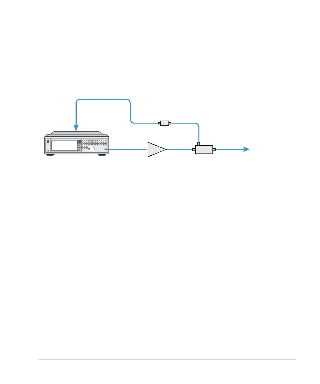
Using External Leveling (N5173B/83B Only)
Recommended Equipment
• Agilent 8474E negative detector
• Agilent 87301D directional coupler
• cables and adapters, as required
Figure 5-21 Typical External Leveling Setup using a Directional Coupler
Configuring the Carrier
1. Press Preset.
2. Set the carrier frequency.
3. Set the power level to 0 dBm:
• If the signal generator has Options 1E1 and 520, set the output attenuator to zero dBm:
a. Press AMPTD > Atten/ALC Control > Atten Hold Off On to On.
b. Press Set Atten > 0 > dB.
c. Press Set ALC Level > 0 > dBm.
Selecting External Leveling
Press AMPTD > Leveling Control > Leveling Mode > Pwr Meter Cont.
Determining the Signal Generator’s Amplitude Range
The maximum output amplitude is frequency dependent. So if you are using multiple frequency
points and there is a need to know the maximum output amplitude for each frequency point, refer to
the “Amplitude” section of the X- Series Data Sheet. Then use this procedure to determine the
maximum amplitude for each band.
Leveled Signal
Signal Generator
Coupler
Amplifier
Negative Detector
RF OUTPUT
ALC INPUT

 Loading...

