Agilent X-Series Signal Generators User’s Guide 183
Basic Digital Operation (Option 653/655/656/657)
Triggering a Waveform
7. On the function generator, configure a TTL signal for the external gating trigger.
8. (Optional) Monitor the waveform:
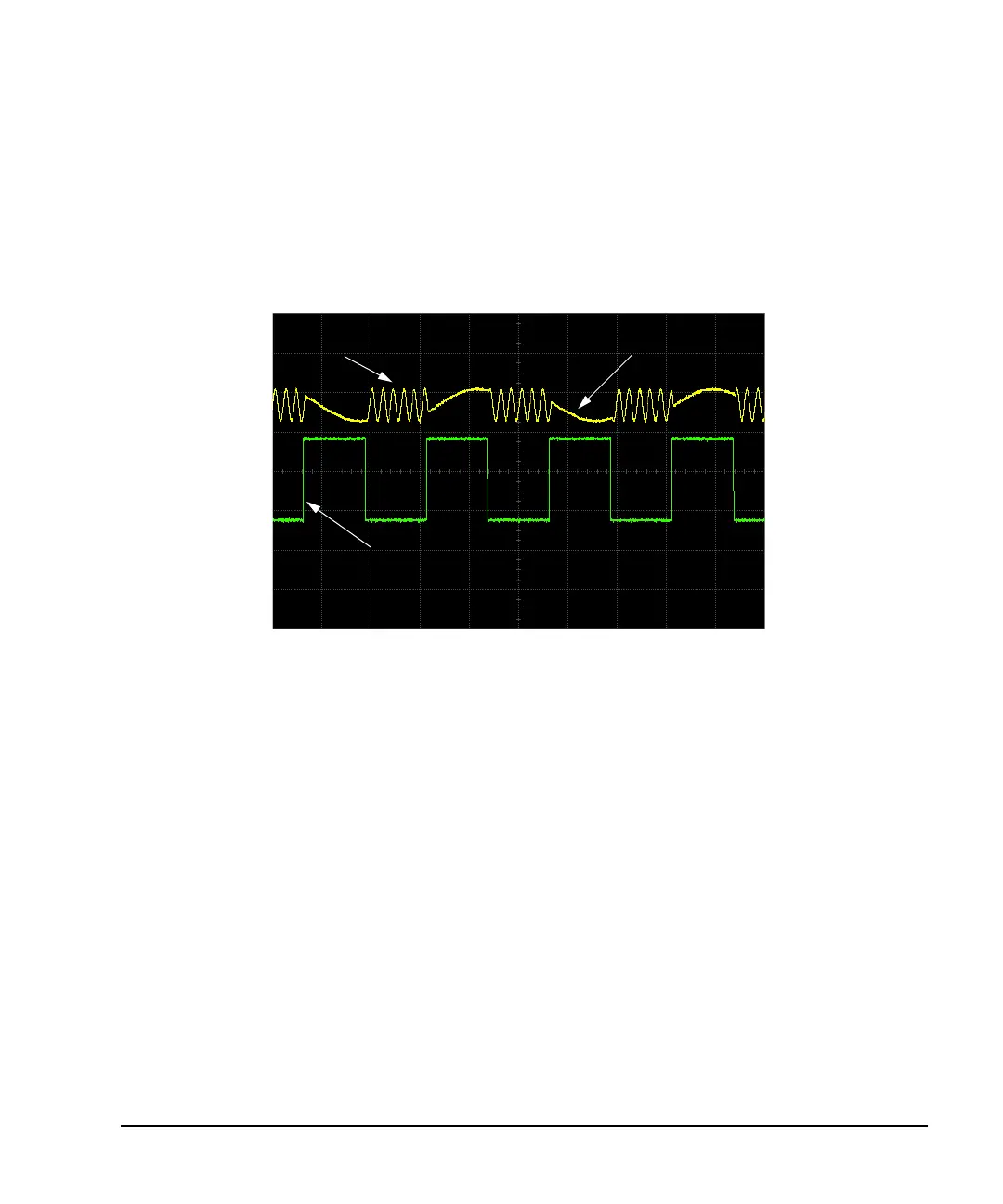
Configure the oscilloscope to display both the output of the signal generator, and the external
triggering signal. You will see the waveform modulating the output during the gate active periods
(low in this example).
The following figure shows an example display.
Modulating Waveform RF Output
Externally Applied Gating Signal
Gate Active = Low

 Loading...

