308 Agilent X-Series Signal Generators User’s Guide
BERT (Option UN7)
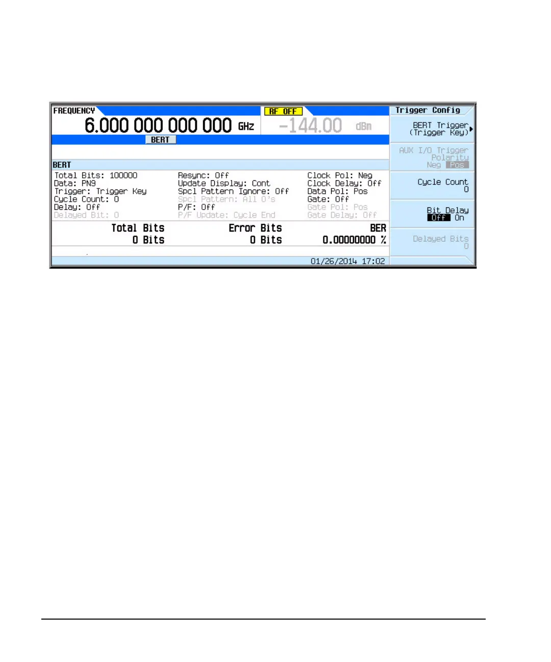
Verifying BERT Operation
Figure 11-16 Configuration Using Custom Digital Modulation
BERT Verification
1. Press BERT Trigger to Immediate.
Notice the cycle counter updating in the lower left- hand corner of the signal generator display.
2. Disconnect the cable connecting the DATA OUT to BER DATA IN connectors.
Notice the No Data annunciator in the lower left corner of the display and the BER result is
approximately 50%. The Error Bits counter updates the error bit count. Re- establishing the
connection turns the annunciator off, and sets the error bits count to 0 bits and BER
0.00000000%.
3. Disconnect the cable connecting the DATA CLK OUT to BER CLK IN connectors.
Notice the No Clock annunciator in the lower left corner of the display. This annunciator turns
off when you re- connect the cable, but the error bits counter and BER % readings indicate loss of
synchronization.
4. Press Return.
Toggle the BERT Off On softkey to Off and to On. You will see the new BER result as shown in the
previous front- panel display with the Error Bits counter reading 0 Bits and BER 0.00000000%.
If the verification procedures produce the expected results, then the signal generator BERT
measurement function is operating correctly. If the above procedure produces unexpected results,
then contact the Agilent Service Center. For a list of Agilent Service Centers, refer to the X- Series
Signal Generators Getting Started Guide.

 Loading...

