Pseudowire Switching
Page 142 7210 SAS M Services Guide
Pseudowire Switching with Protection
Pseudowire switching scales VLL and VPLS services over a multi-area network by removing the
need for a full mesh of targeted LDP sessions between PE nodes. Figure 22 illustrates the use of
pseudowire redundancy to provide a scalable and resilient VLL service across multiple IGP areas
in a provider network.
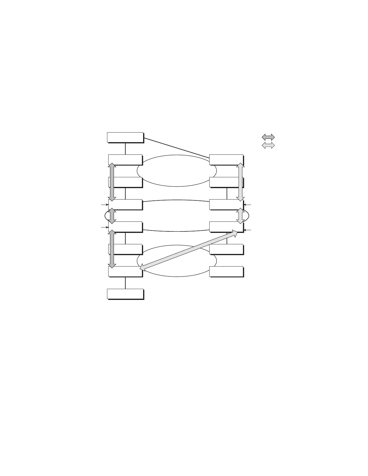
Figure 22: VLL Resilience with Pseudowire Redundancy and Switching
In the network in Figure 22, PE nodes act as masters and pseudowire switching nodes act as slaves
for the purpose of pseudowire signaling. A switching node will need to pass the SAP Interface
Parameters of each PE to the other.T-PE1 sends a label mapping message for the Layer 2 FEC to
the peer pseudowire switching node” for example, S-PE1. It will include the SAP interface
parameters, such as MTU, in the label mapping message. S-PE1 checks the FEC against the local
information and if a match exists, it appends the optional pseudowire switching point TLV to the
FEC TLV in which it records its system address. T-PE1 then relays the label mapping message to
S-PE2. S-PE2 performs similar operations and forwards a label mapping message to T-PE2. The
same procedures are followed for the label mapping message in the reverse direction, for example,
OSSG114-7210M
Core area
Metro area B
Metro area A
Access Node
Access Node
7750 T-PE2
7750 T-PE1
7210
7210
7210 S-PE3
7210 S-PE1
7750 T-PE3
Primary PW
Standby PW
7210
7210
7210
7210 S-PE4
PW switching
SDP6:600
SDP4:400
SDP1:100
SDP3:300
7210 S-PE2
PW switching
PW switching
PW switching

 Loading...